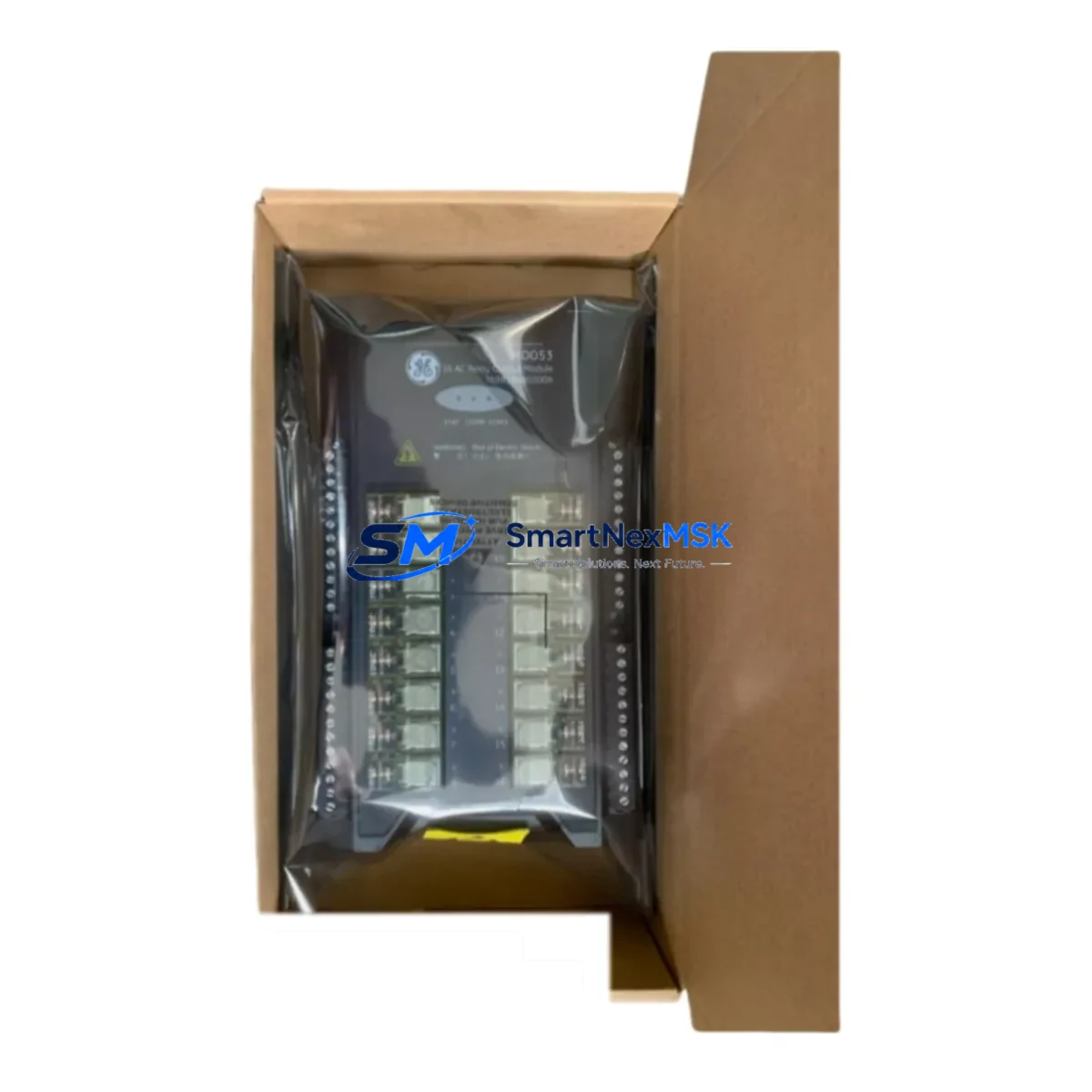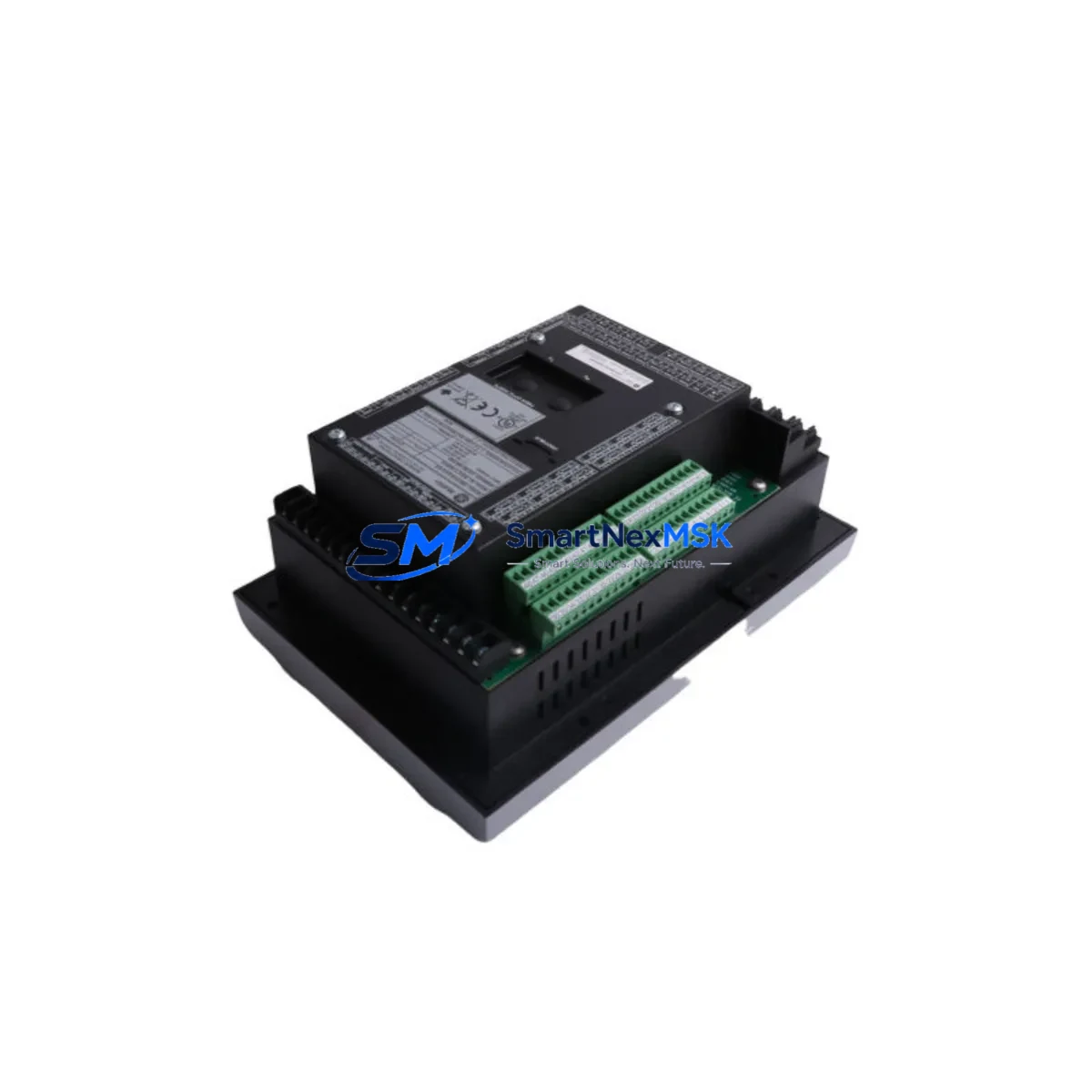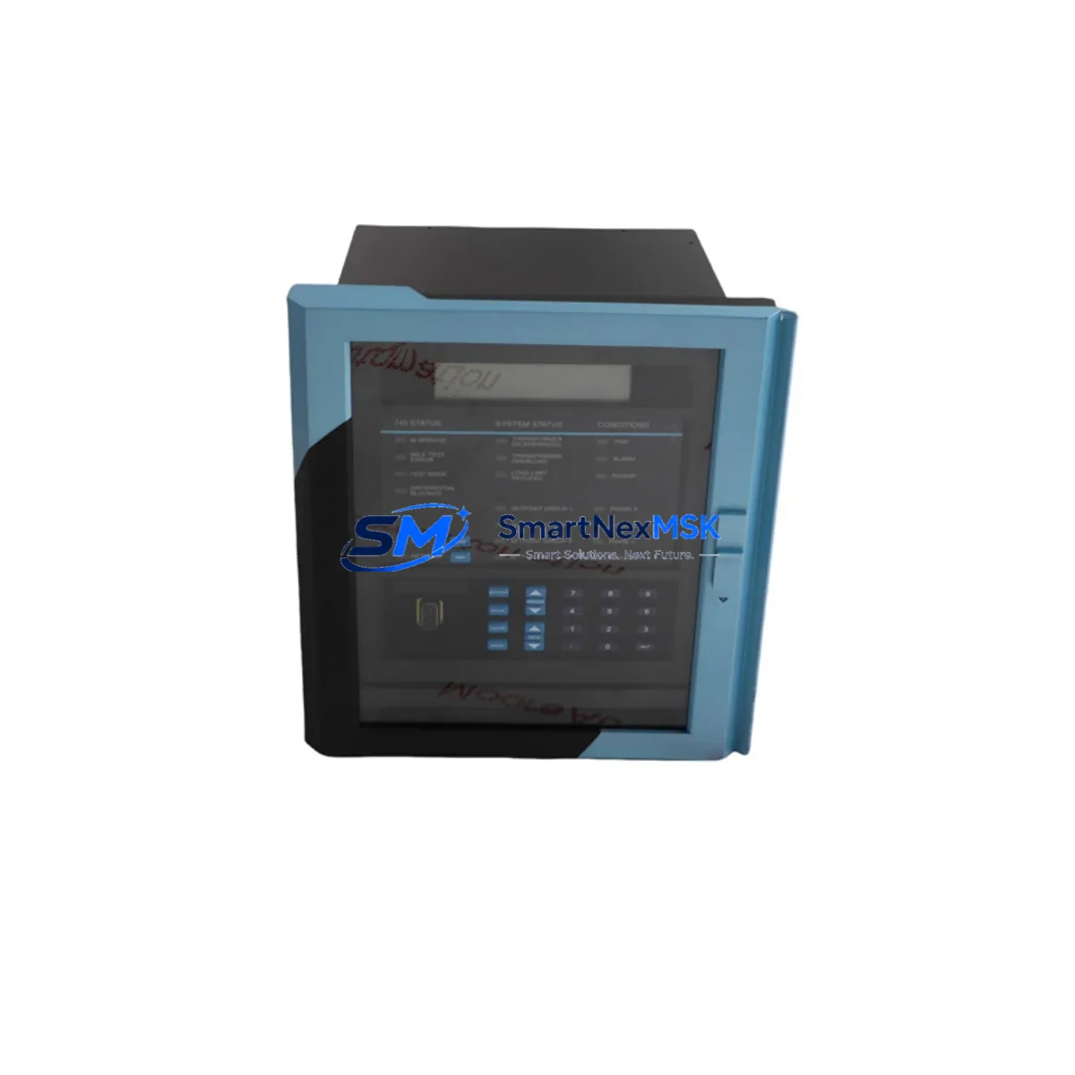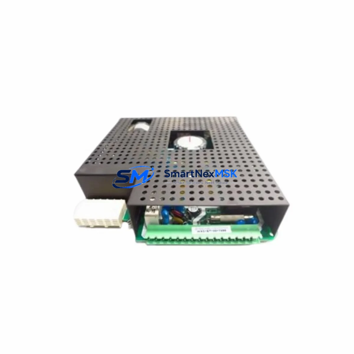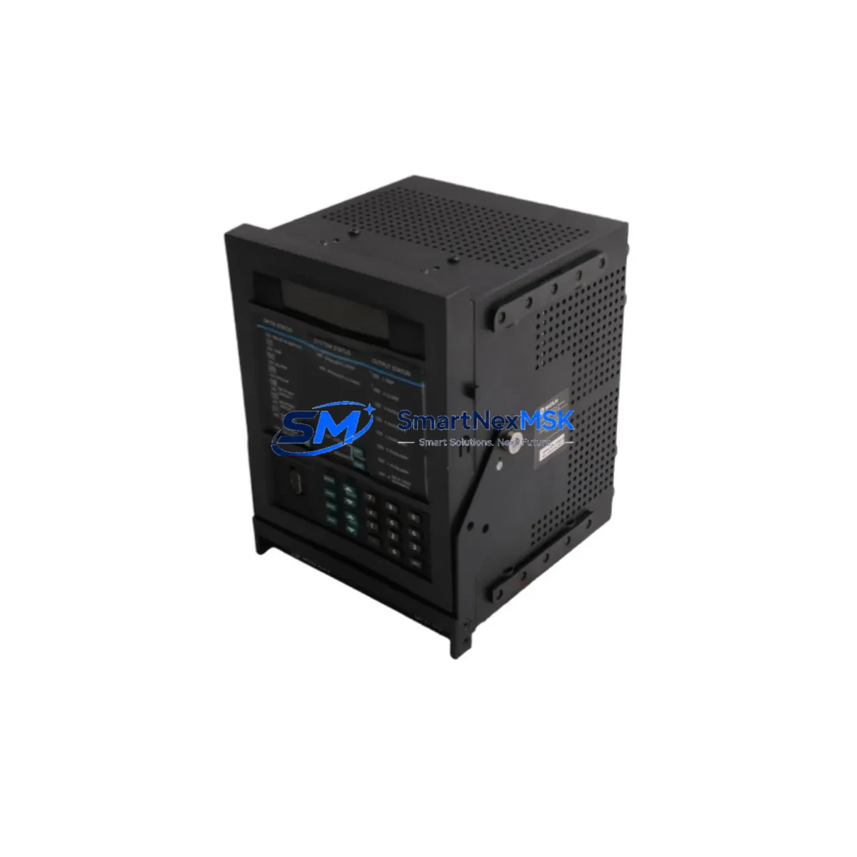
GE Multilin 750-P5-G5-D5-HI-A1-R Retrofit-Ready Motor Protection Relay for 750 Series Control Systems
The GE Multilin 750-P5-G5-D5-HI-A1-R is a fully compatible, retrofit-ready motor protection relay designed as a direct replacement for aging and discontinued units within the GE Multilin 750 Series platform. Whether you are managing a planned upgrade of an existing motor control center, recovering from an unplanned failure, or executing a phased modernization of legacy protection infrastructure, this relay delivers the electrical and functional compatibility required to restore system integrity with minimal disruption to ongoing operations.
The 750 Series has been widely deployed across industries including oil and gas, water treatment, mining, pulp and paper, and heavy manufacturing. As original units reach end-of-service life, sourcing verified replacement hardware becomes a critical bottleneck. This unit is sourced, inspected, and function-tested to meet the original GE Multilin factory specifications, ensuring that your retrofit proceeds without the uncertainty of untested surplus stock.
Upgrade Compatibility Table
| Parameter | Details |
|---|---|
| Compatible Series | GE Multilin 750 Series Motor Protection Relay |
| SKU / Part Number | 750-P5-G5-D5-HI-A1-R |
| Relay Type | Motor Protection Relay (Feeder / Motor Management) |
| Mounting Interface | Panel-mount / rack-compatible; matches original 750 Series cutout dimensions |
| Communication Compatibility | Modbus RTU, DNP3, IEC 60870-5-103 (verify firmware revision against site SCADA) |
| Terminal Wiring | Rear terminal block; verify CT secondary wiring (1A or 5A) and VT connections before installation |
| Power Supply Input | Confirm auxiliary power supply voltage (AC/DC) matches site specification prior to energization |
| Replacement Recommendation | Direct drop-in for 750-P5-G5-D5-HI-A1-R; settings backup from original unit recommended before swap |
| Commissioning Notes | Re-upload protection settings file; verify CT ratio, pickup thresholds, and trip curves post-installation |
| Warranty | 12-Month Warranty — covers manufacturing defects and functional failures under normal operating conditions |
Retrofit Planning for Existing Automation Systems
A successful retrofit of the GE Multilin 750-P5-G5-D5-HI-A1-R requires systematic pre-installation planning across several interdependent subsystems. Before removing the original unit, engineers should use the GE EnerVista 750 Setup software to export the full settings file, including all protection element setpoints, I/O assignments, communication parameters, and relay identification data. This backup is essential — it eliminates the risk of losing years of site-specific tuning accumulated during the relay’s operational life.
On the hardware side, the control cabinet housing the 750 Series relay typically includes several companion components that must be verified for compatibility. The auxiliary power supply feeding the relay — often a dedicated 24 VDC or 120 VAC module — should be load-tested to confirm it can support the replacement unit’s inrush and steady-state draw. Current transformer secondary circuits (typically 1A or 5A) must be confirmed against the relay’s CT input rating, as a mismatch here will cause metering errors and incorrect protection operation.
In systems where the 750 relay interfaces with a GE Multilin 469 Motor Management Relay or a GE Multilin 339 Motor Protection Relay on adjacent feeders, the inter-relay communication scheme — whether via hardwired contact outputs or serial Modbus links — must be documented and re-verified after the swap. Similarly, if the motor control center includes a GE Multilin SR760 or SR735 feeder protection relay sharing a common communication bus, the bus address and baud rate settings of the replacement 750-P5-G5-D5-HI-A1-R must be configured to match the original before the communication link is restored.
For sites using a GE D20 or D25 RTU as the upstream SCADA concentrator, the DNP3 or Modbus point map associated with the original relay should be retrieved from the RTU configuration database. The replacement relay must be programmed with identical register assignments to avoid data mapping errors in the control room. Where the site uses a GE iFIX or Wonderware SCADA HMI, the HMI faceplate for the motor feeder should be tested in simulation mode after the relay is back online to confirm that all analog values, status bits, and alarm points are populating correctly.
I/O wiring to field devices — including motor starter auxiliary contacts, thermistor inputs, and emergency stop circuits — should be photographed and labeled before disconnection. The GE Multilin 750 Series uses a rear terminal block layout that is consistent across the product family, but individual site wiring practices vary. A terminal-by-terminal verification against the original as-built drawings is the most reliable method to ensure correct reconnection. If the original drawings are unavailable, the wiring can be reconstructed from the relay’s I/O assignment settings exported during the pre-removal backup.
Downtime Control During System Migration
Minimizing production downtime during a 750 Series relay replacement requires a structured swap procedure that preserves the original protection logic and avoids inadvertent motor trips or control interruptions. The recommended approach is to schedule the physical swap during a planned maintenance window, with the motor isolated and locked out in accordance with site LOTO procedures.
Before de-energizing the original relay, confirm that the settings backup is complete and verified. Once the replacement 750-P5-G5-D5-HI-A1-R is physically installed and wired, restore power to the auxiliary supply first and confirm the relay boots without fault indications. Upload the saved settings file via EnerVista 750 Setup and perform a full settings verification — do not assume the upload was error-free without a parameter-by-parameter comparison against the backup.
With settings confirmed, perform a secondary injection test on the CT inputs if site conditions permit, verifying that the relay’s metering values match the known load current. Check all digital input states against the field device status before enabling protection elements. Restore the Modbus or DNP3 communication link and confirm that the upstream SCADA or DCS — whether a GE Mark VIe, a Honeywell Experion, or an ABB 800xA system — is receiving valid data from the relay before returning the motor to service.
This structured approach typically allows a complete relay swap to be completed within a two- to four-hour maintenance window, keeping unplanned production loss to a minimum while ensuring that the replacement relay is fully commissioned and protection-ready before the motor is re-energized.
Retrofit Support FAQ
Q1: Is the 750-P5-G5-D5-HI-A1-R a direct drop-in replacement for my existing GE Multilin 750 Series unit?
Yes. The 750-P5-G5-D5-HI-A1-R is a form-fit-function replacement for the original GE Multilin 750 Series relay with the same option codes. The rear terminal layout, mounting dimensions, and firmware architecture are consistent with the original factory unit. You should verify that the option codes in the part number match your site’s specific I/O, communication, and power supply configuration before installation.
Q2: What commissioning steps are required after installing the replacement relay?
After physical installation and wiring verification, upload the settings backup from the original relay using GE EnerVista 750 Setup software. Verify all protection element setpoints, CT ratios, I/O assignments, and communication parameters. Restore the serial or Ethernet communication link and confirm SCADA data integrity. Perform a functional test of all digital outputs before returning the motor to service.
Q3: How do I verify wiring compatibility between the replacement relay and my existing control cabinet?
Compare the terminal block wiring against the original as-built drawings or the wiring reconstruction exported from the original relay’s settings file. Pay particular attention to CT secondary polarity, VT phase connections, auxiliary power supply polarity, and the assignment of digital input and output terminals. Photograph all wiring before disconnection to provide a reference during reconnection.
Q4: What does the 12-month warranty cover, and how is the unit tested before shipment?
Every 750-P5-G5-D5-HI-A1-R unit is function-tested prior to shipment to verify power-up, communication port operation, I/O functionality, and metering accuracy. The 12-month warranty covers manufacturing defects and functional failures under normal operating conditions from the date of delivery. Units that fail during the warranty period are repaired or replaced at no charge. Contact [email protected] for warranty claims or pre-shipment test reports.
© 2026 SMARTNEXMSK. All rights reserved.
Original Source: https://smartnexmsk.com
Contact: [email protected] | +86 18259474341