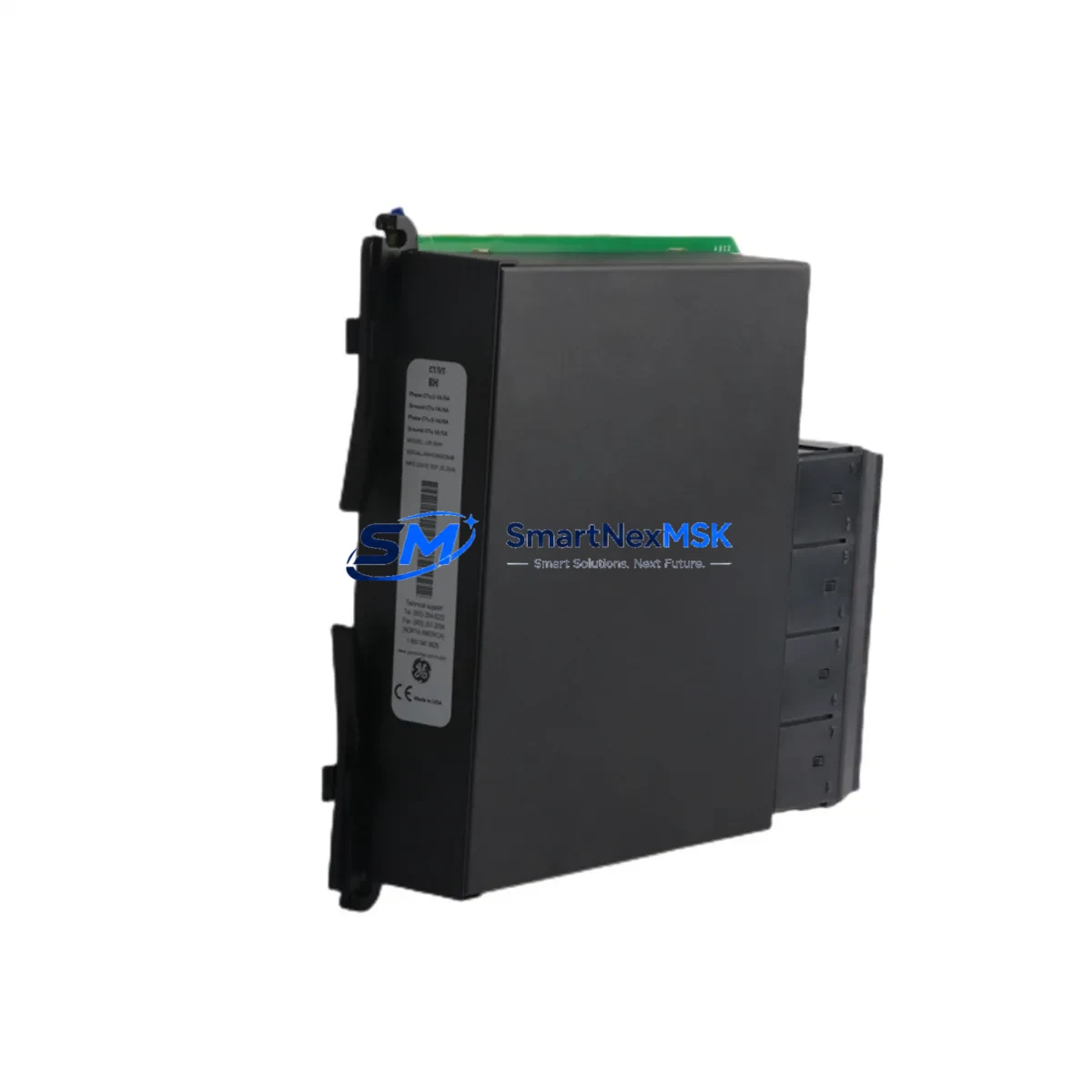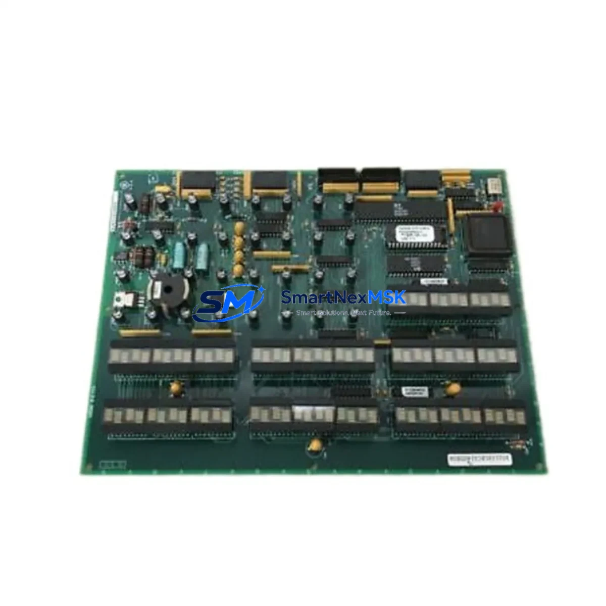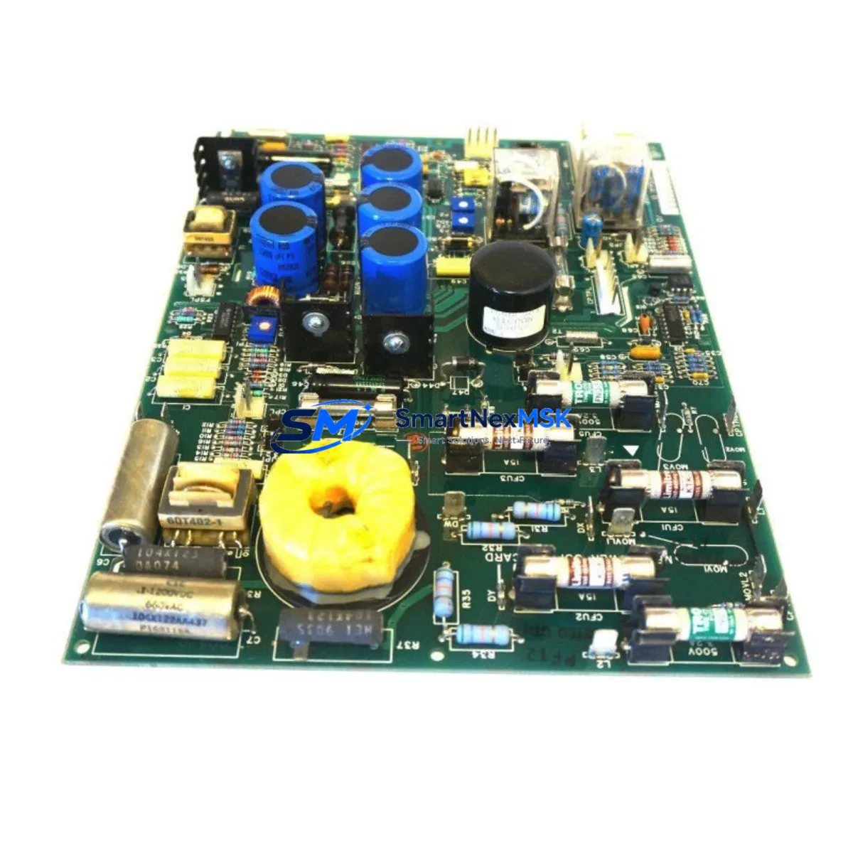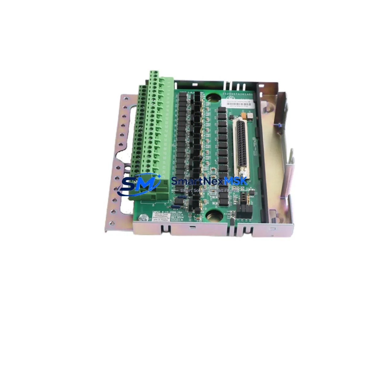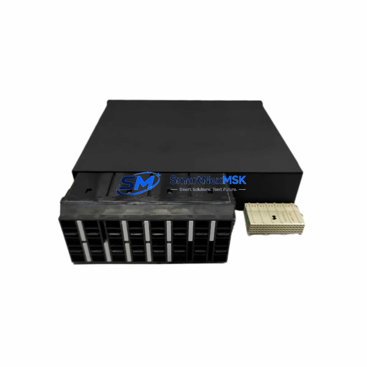
GE UR6GH Maintenance-Ready Spare for UR Series Automation
The GE UR6GH is an original Digital I/O Module designed for the GE UR Series protection and control platform — one of the most widely deployed relay and automation systems in power generation, transmission, and heavy industrial environments. When a UR6GH fails or reaches end-of-service life, every minute of unplanned downtime translates directly into production loss, safety risk, and costly emergency procurement. Stocking a verified replacement spare is the single most effective strategy for rapid fault recovery and continuous system availability.
This listing supplies a genuine, original GE UR6GH Digital I/O Module — not a clone or third-party substitute. Each unit is individually inspected, function-tested, and shipped with full traceability documentation. Whether you are executing a planned outage replacement, responding to an unexpected relay trip, or building out your critical-spare inventory for a multi-bay switchgear room, the UR6GH is ready to install and commission without firmware re-flashing or hardware modification.
Spare Maintenance Table
| Parameter | Specification / Detail |
|---|---|
| Part Number / SKU | UR6GH |
| Brand | General Electric (GE Grid Solutions) |
| Series | UR Series (Universal Relay) |
| Module Type | Digital I/O Module |
| Form Factor | UR Chassis Plug-in Card (Slot-compatible) |
| Digital Inputs | 16 × Optically Isolated Digital Inputs |
| Digital Outputs | 8 × Form-A / Form-C Relay Outputs (model-dependent) |
| Input Voltage Range | 24 VDC – 250 VDC (wet contact compatible) |
| Communication Interface | Internal UR backplane bus |
| Compatibility | GE UR Series: C30, C60, C70, D30, D60, F35, F60, L30, L60, L90, M60, N60, T35, T60 |
| Operating Temperature | -20°C to +60°C |
| Mounting | Direct chassis slot insertion — no tools required |
| Origin | China (CN) |
| Condition | Original Spare — New / Refurbished Available |
| Pre-shipment Testing | Full functional test performed on every unit |
| Warranty | 12 Months from date of shipment |
| Lead Time | In-stock: ships within 2 business days |
| Maintenance Recommendation | Replace every 10–15 years or upon first I/O fault indication |
Maintenance Planning for Continuous Operation
Replacing a UR6GH Digital I/O Module is rarely an isolated task. Experienced maintenance engineers know that a failing I/O card is often a symptom of broader stress across the control cabinet. Before returning the system to service, a disciplined site inspection should cover the following associated components:
Power Supply Module (e.g., UR6PP / UR6PT): Verify DC rail voltage stability. A degraded power supply is a leading cause of intermittent I/O faults and can damage a newly installed UR6GH if left unaddressed. Check output ripple and confirm the supply is within GE’s specified tolerance band.
CPU / Main Processor Card: Confirm firmware version compatibility with the replacement UR6GH. Mismatched firmware between the CPU module and a new I/O card can cause configuration errors or prevent the relay from entering service mode. Download the latest settings file from EnerVista UR Setup before re-commissioning.
UR Chassis Backplane: Inspect the backplane connector pins for oxidation, mechanical damage, or heat discoloration. A compromised backplane will cause erratic communication between the UR6GH and the CPU, producing false alarms or missed trip signals.
Terminal Blocks and Field Wiring: Re-torque all I/O terminal screws to the manufacturer’s specification. Loose connections on digital input circuits are a primary source of nuisance trips and can mask the true root cause of the original fault. Inspect insulation on field cables for heat damage or abrasion.
Auxiliary Relay Modules: If the UR6GH drives external interposing relays or output relay modules, test each relay coil resistance and contact continuity. Worn relay contacts can cause the new I/O module to report output faults even when the card itself is healthy.
Communications Module (e.g., UR6CH — RS-485 / IEC 61850 / DNP3): Verify that SCADA polling and event logging resume correctly after the I/O module swap. A communications module that was marginal before the outage may fail to re-establish the link once the chassis is powered down and restarted.
Signal Isolators and Transducers: For analog-adjacent I/O circuits, check any signal isolators or loop-powered transducers connected to the digital input wiring. These devices can develop leakage currents that falsely assert digital inputs on the UR6GH, leading to misdiagnosis of the module as faulty.
Fuses and Circuit Protection: Replace any blown or discolored fuses in the I/O wiring circuits. A fuse that has operated once is thermally stressed and should be treated as a consumable spare. Stock GE-rated fuse types appropriate for the UR panel’s protection scheme.
HMI / Front Panel Display Module: After re-commissioning, use the UR relay’s front-panel HMI or EnerVista software to run a full I/O self-test. Confirm that all digital inputs and outputs report correctly in the relay’s actual values menu before closing the cabinet.
Fiber Optic or Copper Communication Cables: If the UR relay is part of a line differential or bus differential protection scheme, inspect inter-relay communication cables for continuity and signal integrity. A damaged fiber patch cord can prevent the protection scheme from operating correctly even after a successful I/O module replacement.
Site Replacement Workflow
Step 1 — Isolation and Permit: Obtain a signed work permit and isolate the UR relay from all live circuits per your site’s lockout/tagout procedure. Record all current settings using EnerVista UR Setup before removing any hardware.
Step 2 — Module Extraction: With the chassis de-energized, release the UR6GH card locking mechanism and slide the module straight out of its slot. Avoid lateral force to protect the backplane connector. Place the removed module in an anti-static bag for return or failure analysis.
Step 3 — Visual Inspection: Before inserting the replacement UR6GH, inspect the chassis slot for debris, bent pins, or signs of thermal damage. Clean the slot with dry compressed air if necessary.
Step 4 — Module Insertion: Align the replacement UR6GH with the chassis guide rails and slide firmly until the card seats fully and the locking tab engages. No jumper or DIP switch configuration is required — the UR6GH is auto-configured by the CPU upon power-up.
Step 5 — Power-Up and Self-Test: Restore control power and observe the relay’s boot sequence. The UR6GH should be recognized automatically. Navigate to the I/O self-test menu and verify all digital inputs and outputs are functional before re-energizing field circuits.
Step 6 — Settings Restore and Commissioning: Download the saved settings file back to the relay via EnerVista. Perform a functional trip test on each output circuit to confirm correct operation. Document the replacement in your maintenance management system (CMMS) and update the spare parts register.
This structured workflow minimizes re-energization risk, ensures full system compatibility, and reduces mean time to repair (MTTR) — keeping your protection scheme available and your process running.
Spare Parts Support FAQ
Q1: Is the UR6GH compatible with all GE UR Series relay models?
The UR6GH is designed for the GE Universal Relay (UR) platform and is slot-compatible with the full UR Series chassis, including the C30, C60, C70, D30, D60, F35, F60, L30, L60, L90, M60, N60, T35, and T60. Always confirm the chassis slot assignment and firmware version with your relay’s order code before installation. If you are unsure, contact us with your relay’s full model number and we will verify compatibility before shipment.
Q2: What does the 12-month warranty cover?
Every UR6GH shipped from our inventory is covered by a 12-month warranty from the date of shipment. The warranty covers manufacturing defects, functional failures under normal operating conditions, and DOA (dead-on-arrival) units. Each module undergoes a full functional test prior to dispatch. In the event of a warranty claim, we provide a replacement unit or full refund — no lengthy RMA delays.
Q3: How should I manage UR6GH spare inventory for a multi-relay substation?
For substations with 5 or more UR Series relays, we recommend maintaining a minimum of one UR6GH spare per 5 installed units, with at least one unit always on-shelf. For critical protection applications (line differential, bus protection), consider a 1:3 spare ratio. Coordinate your spare parts review with your annual maintenance outage schedule to rotate stock and avoid shelf-life concerns.
Q4: Can you supply UR6GH units for emergency same-week dispatch?
Yes. In-stock UR6GH units ship within 2 business days of order confirmation. For genuine emergency situations — unplanned outages, forced outages, or protection system failures — contact our sales team directly at [email protected] or call +86 18259474341 to discuss priority dispatch options. We support industrial customers across multiple time zones and can coordinate with freight forwarders for expedited international delivery.
© 2026 SMARTNEXMSK. All rights reserved.
Original Source: https://smartnexmsk.com
Contact: [email protected] | +86 18259474341