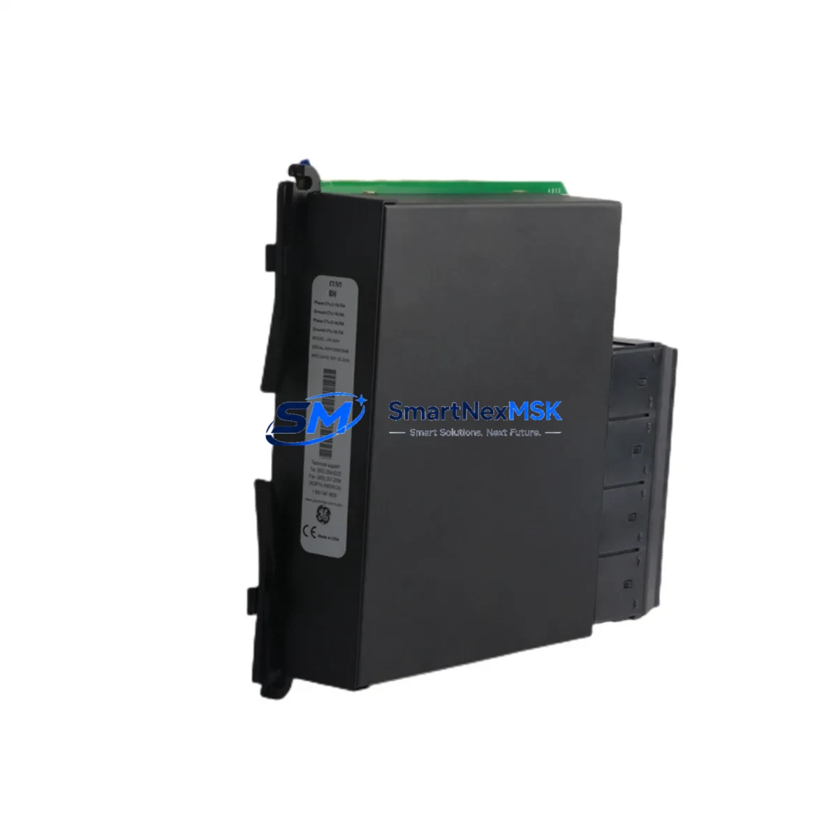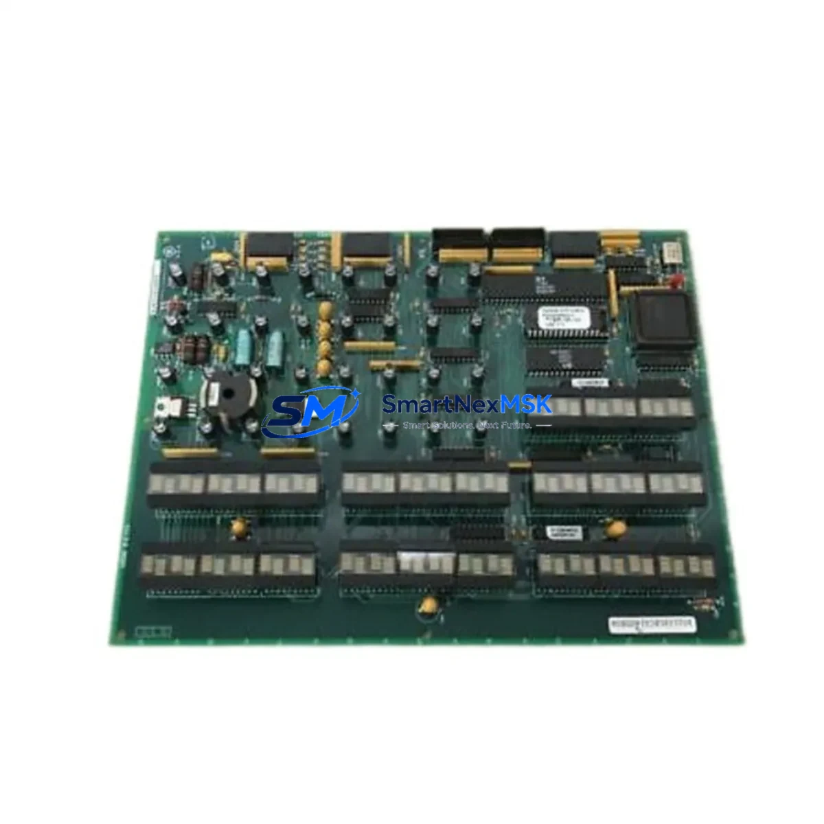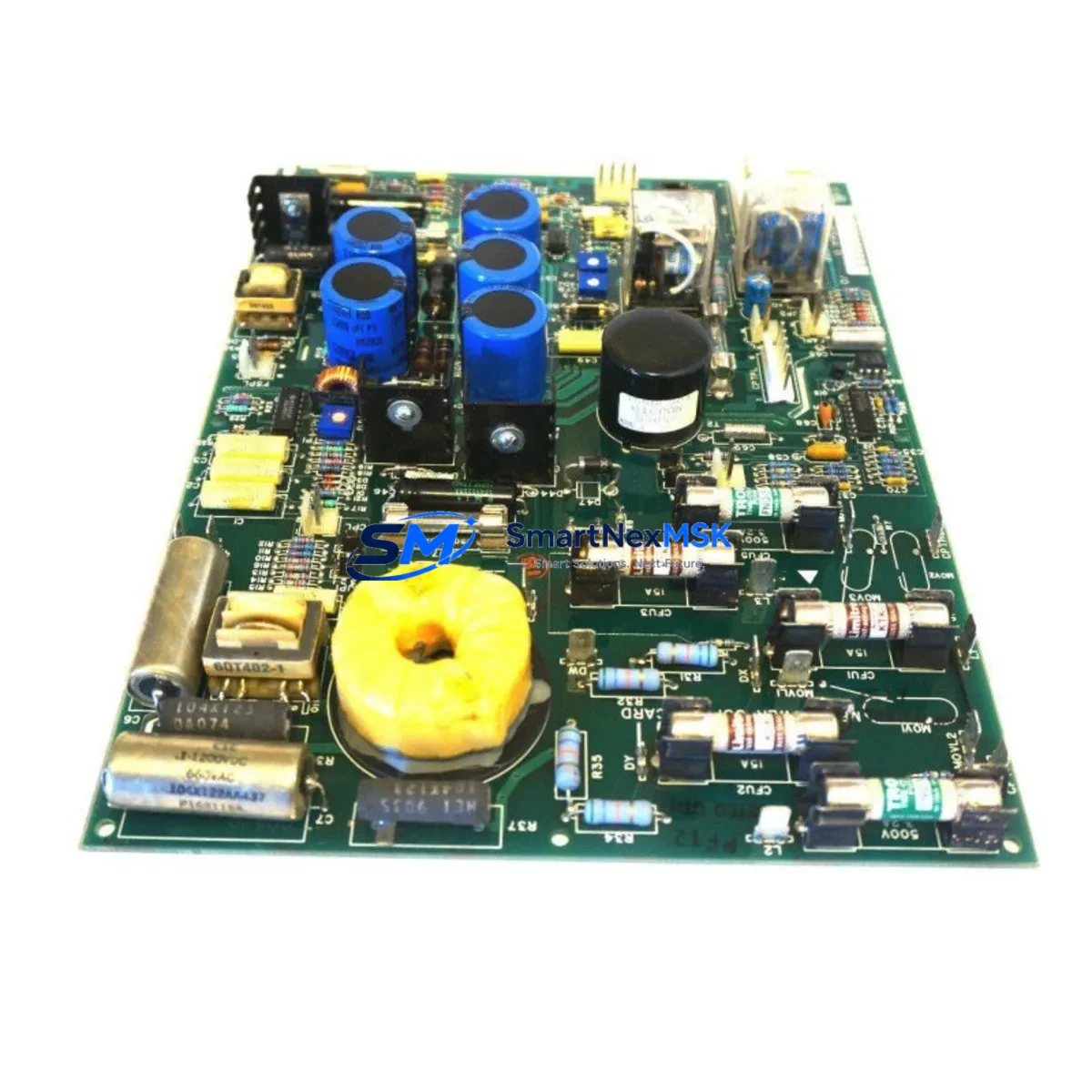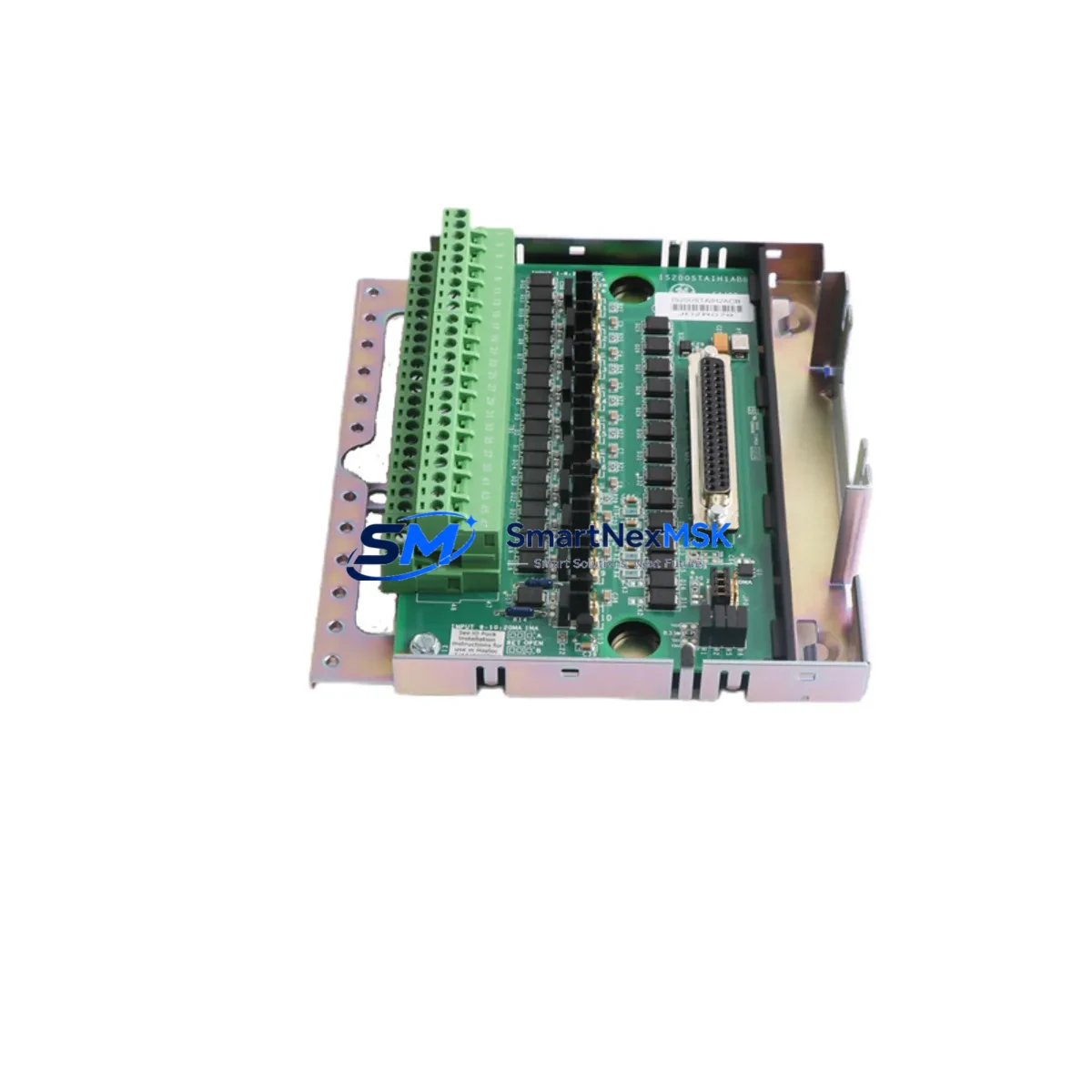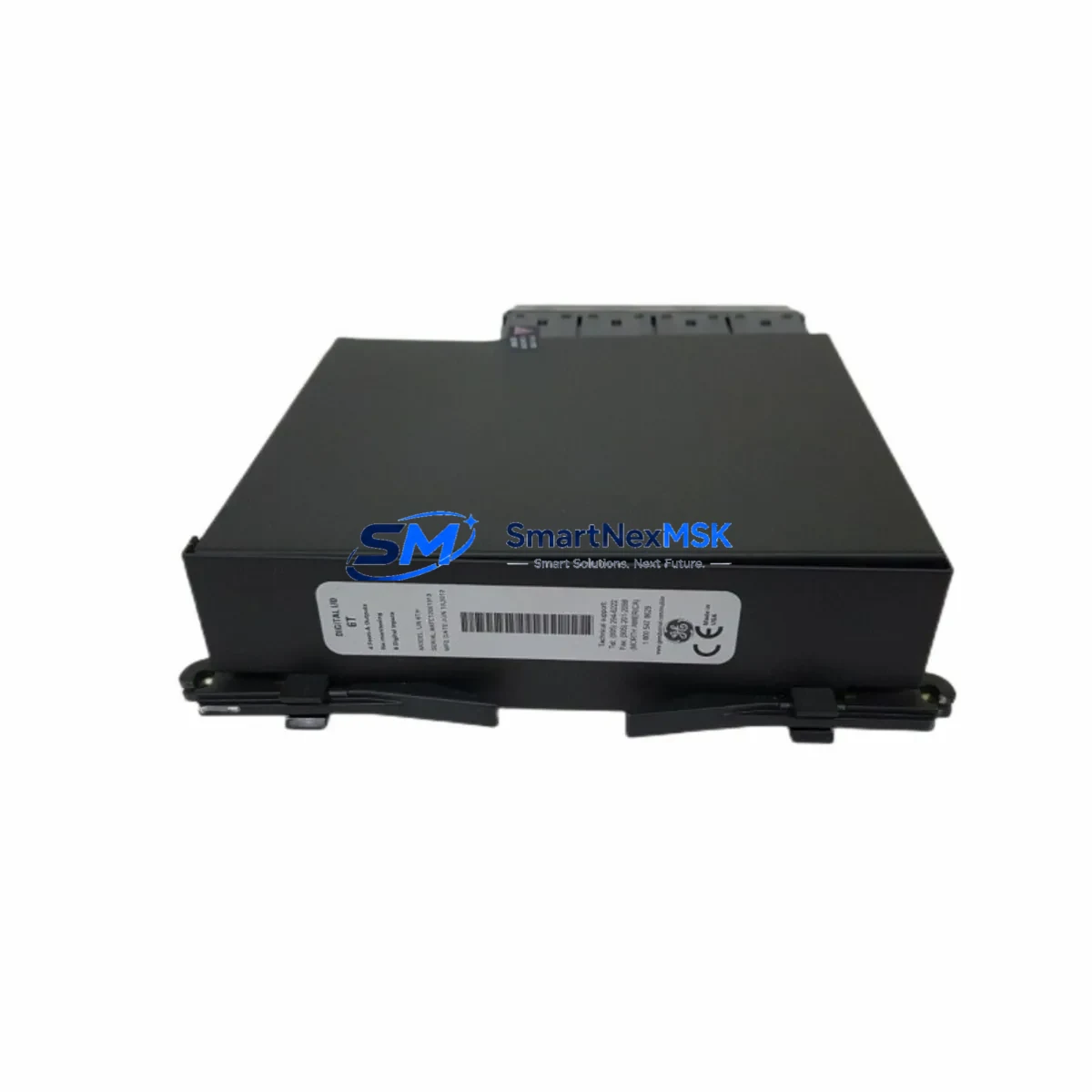
GE UR6TH Retrofit-Ready Protection Relay for UR Series Control Systems
The GE UR6TH is a high-performance protection relay module engineered for seamless integration into GE Multilin UR Series control architectures. Designed with retrofit-first engineering, the UR6TH addresses the growing demand for reliable, drop-in replacements in aging protection and control systems — particularly where legacy UR-platform relays have reached end-of-life or are no longer available through standard supply channels.
Whether you are modernizing a substation protection scheme, replacing a discontinued relay in a generation facility, or upgrading a transmission line protection panel, the UR6TH delivers the compatibility, configurability, and field-proven reliability that industrial engineers require. Its hardware architecture aligns with the UR platform’s universal chassis design, allowing installation into existing UR-series racks and backplanes without structural modification to the control cabinet.
Upgrade Compatibility Table
| Parameter | Details |
|---|---|
| Compatible Platform | GE Multilin UR Series (UR, URplus) |
| Chassis / Rack Fit | Standard UR universal chassis; no mechanical modification required |
| Backplane Interface | UR-series backplane connector; verify slot addressing before installation |
| Communication Protocols | IEC 61850 GOOSE, DNP3, Modbus RTU/TCP, IEC 60870-5-103 |
| Typical Replacements | UR6TH replaces discontinued UR-platform relay variants in same function class |
| Terminal Wiring | Compatible with existing CT/VT wiring; confirm terminal block pinout against original relay drawing |
| Commissioning Tool | EnerVista UR Setup software (latest version recommended) |
| Firmware Compatibility | Verify firmware revision matches site SCADA/HMI driver version |
| Retrofit Recommendation | Perform settings migration via EnerVista export/import; validate logic equations post-swap |
| Warranty | 12 Months — covers manufacturing defects, functional failure under normal operating conditions |
Retrofit Planning for Existing Automation Systems
A successful UR6TH retrofit begins well before the relay arrives on site. Engineers should start by auditing the existing protection scheme: pull the original relay’s settings file from EnerVista UR Setup, document all active protection elements, logic equations, and output contact assignments, and cross-reference them against the UR6TH’s function block library. In most UR-platform upgrades, the settings file can be imported directly — but element mapping must be verified manually, particularly for schemes that use FlexLogic™ custom logic.
On the hardware side, confirm that the UR-series universal chassis and backplane are in serviceable condition. Inspect the backplane ribbon connectors and verify that the slot address DIP switches are set correctly for the UR6TH’s intended module position. If the existing installation includes a UR CPU module (such as the 9G or 9H processor card), confirm firmware compatibility between the CPU and the UR6TH before energizing. Mismatched firmware revisions are a common source of communication faults during commissioning.
For sites running IEC 61850 schemes, export the existing IED’s CID file and validate that the UR6TH’s logical node structure matches the SCADA or substation automation system’s expectations. Where the original relay used DNP3 or Modbus RTU over an RS-485 serial link, verify that the UR6TH’s communications module — typically a UR 9E or 9F communications card — is configured with the correct baud rate, parity, and device address before connecting to the RTU or gateway.
Power supply compatibility is another critical checkpoint. The UR6TH accepts a wide DC input range, but confirm that the existing station battery or DC/DC converter module in the control cabinet can supply adequate current under worst-case load. If the panel also houses a UR I/O module for digital input expansion or a UR transducer input card for analog measurements, verify that the total backplane current draw remains within the chassis power budget.
HMI integration should be validated in parallel. If the substation uses a GE iFIX or third-party SCADA HMI, update the driver configuration to reflect the UR6TH’s data model. For sites using a UR front-panel HMI or a remote annunciator panel, confirm that the relay’s user-programmable display pages and LED assignments are reconfigured to match the original operator interface layout. This step is frequently overlooked and can cause operator confusion during the first post-retrofit alarm event.
Finally, before closing the control cabinet, perform a complete loop test: inject test currents and voltages using a relay test set, verify all protection element pickups and timing, exercise each output contact, and confirm SCADA point mapping end-to-end. Document the as-left settings file and store it in the site’s configuration management system. All UR6TH units supplied by SMARTNEXMSK are pre-tested and shipped with a 12-month warranty covering manufacturing defects and functional failure under normal operating conditions.
Downtime Control During System Migration
Minimizing protection outage time is the primary operational constraint in any relay retrofit. For the UR6TH replacement, the recommended approach is a staged swap: pre-configure the new relay offline using EnerVista UR Setup with the exported settings file from the outgoing unit, so that the replacement arrives at the switchyard already loaded with the correct protection settings, logic, and communications parameters.
During the physical swap window, follow a strict sequence: isolate the circuit breaker, open the relay test switch (if fitted), disconnect the UR6TH’s CT and VT wiring using the terminal block’s shorting facility, remove the old relay from the chassis, seat the UR6TH, reconnect wiring, and restore the test switch. With a pre-configured relay, the commissioning phase reduces to a targeted verification — typically 2 to 4 hours for a single feeder protection relay — rather than a full settings entry and loop test from scratch.
For critical bus or transformer protection applications where any protection gap is unacceptable, coordinate with the system operator to arrange a temporary backup protection scheme using a portable relay test set or a spare relay in bypass mode before beginning the swap. Preserve the original relay’s settings file and event records as a reference baseline. The UR6TH’s non-volatile memory retains all settings through power cycling, eliminating the risk of settings loss during transport or installation.
Retrofit Support FAQ
Q1: Is the UR6TH a direct drop-in replacement for other UR-series relays in the same function class?
A: In most cases, yes — the UR6TH shares the UR platform’s universal chassis form factor and backplane interface. However, you must verify the specific relay type code (e.g., distance, differential, overcurrent) and confirm that the UR6TH’s ordered configuration includes the required function modules. Settings migration via EnerVista is supported, but a full settings review is mandatory before energizing.
Q2: What communications protocols does the UR6TH support, and will it work with my existing RTU?
A: The UR6TH supports IEC 61850 (GOOSE and MMS), DNP3 (serial and TCP/IP), Modbus RTU/TCP, and IEC 60870-5-103. Compatibility with your RTU depends on the communications card fitted and the RTU’s driver version. Provide your RTU model and protocol version when ordering so we can confirm the correct communications module configuration.
Q3: How do I verify wiring compatibility before removing the old relay?
A: Download the UR6TH’s terminal block diagram from the GE Multilin documentation library and compare it against the existing relay’s wiring schedule. Pay particular attention to CT polarity, VT phase rotation, binary input voltage levels, and output contact ratings. In most UR-series retrofits, the existing wiring can be reused without modification — but always verify against the as-built drawings for your specific installation.
Q4: What does the 12-month warranty cover, and what is the return process?
A: The 12-month warranty covers manufacturing defects and functional failure under normal operating conditions from the date of shipment. It does not cover damage resulting from incorrect installation, overvoltage, or unauthorized modification. To initiate a warranty claim, contact [email protected] with the order number, relay serial number, and a description of the fault. We will arrange return shipping and provide a replacement or repair within the agreed lead time.
© 2026 SMARTNEXMSK. All rights reserved.
Original Source: https://smartnexmsk.com
Contact: [email protected] | +86 18259474341