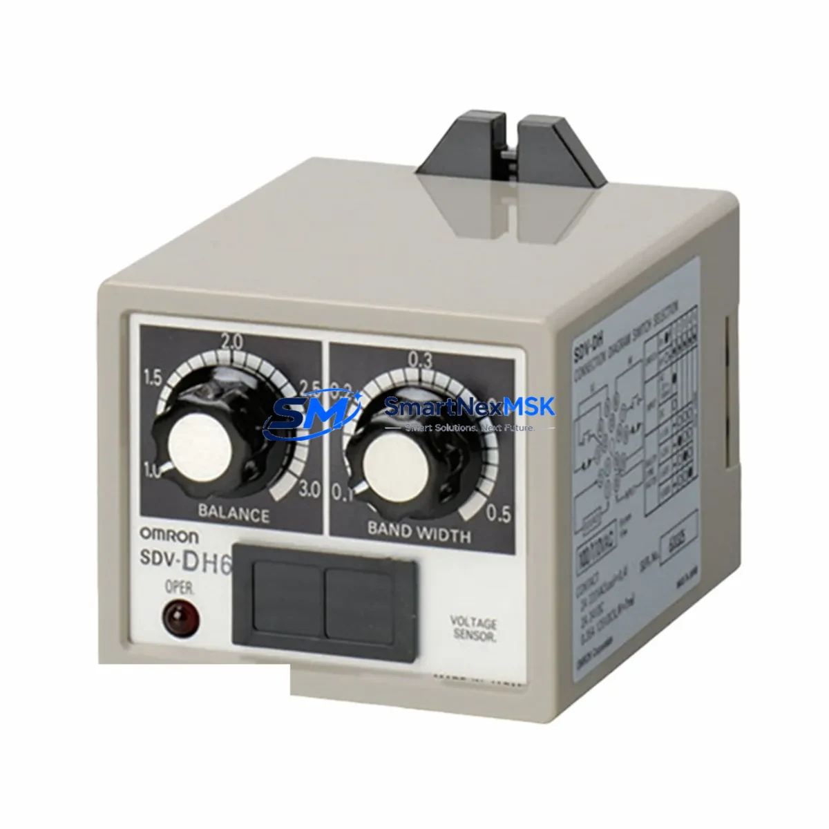
OMRON SDV-DH7: Retrofit-Ready Voltage Sensing Relay for SDV-DH Series Control Systems
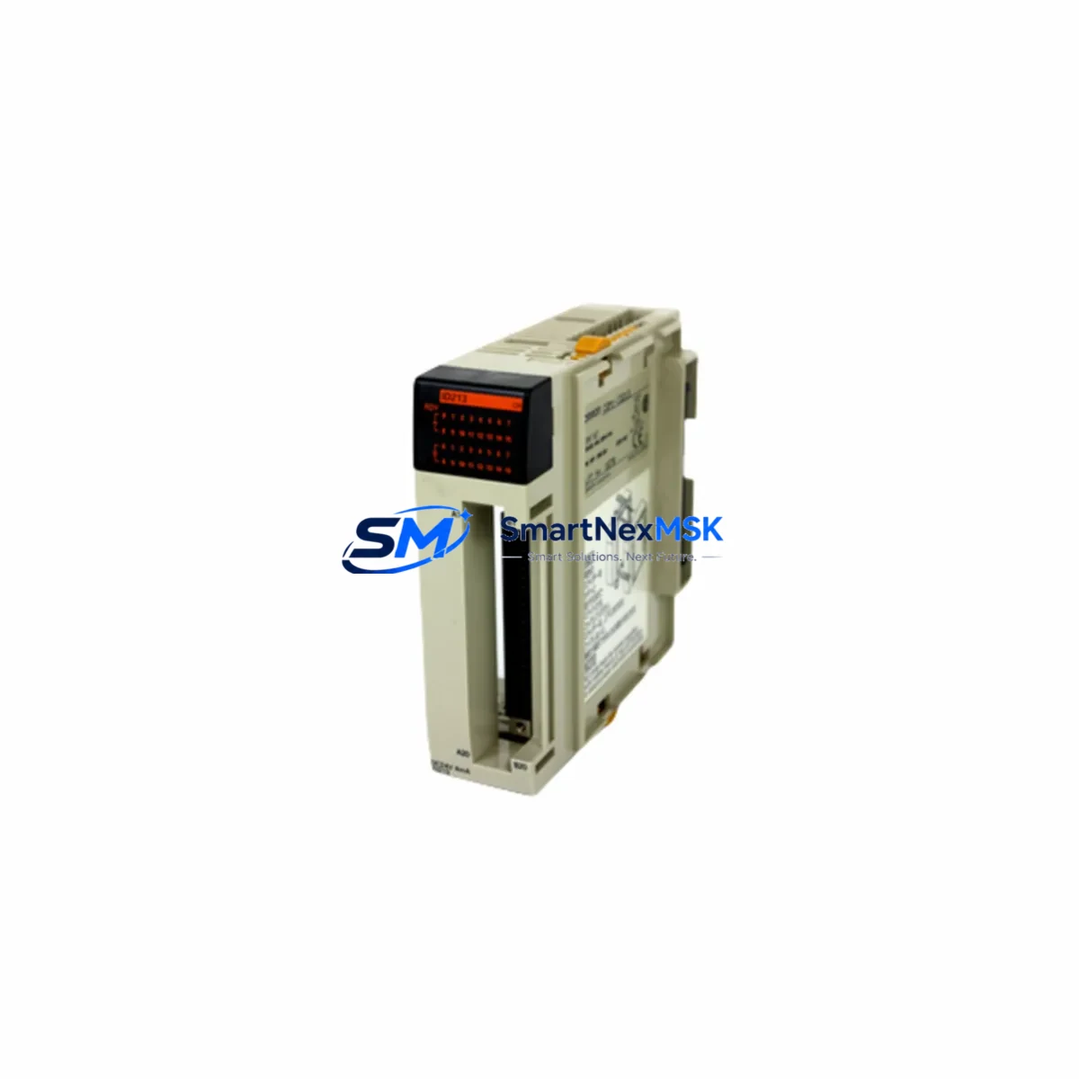
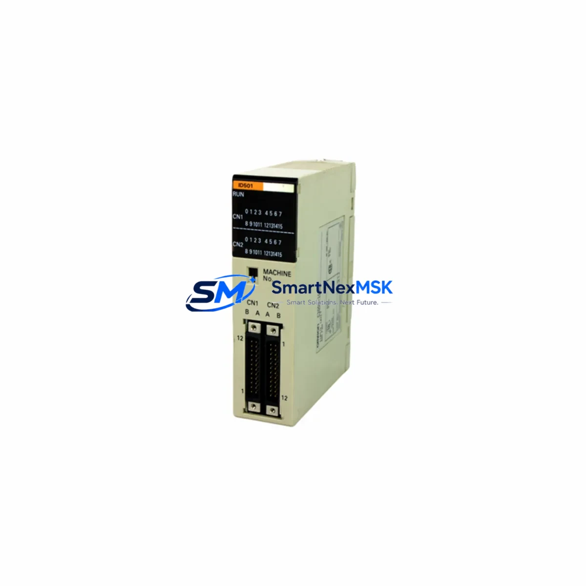
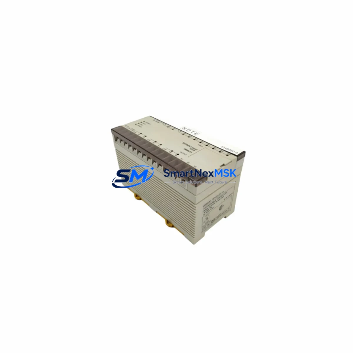
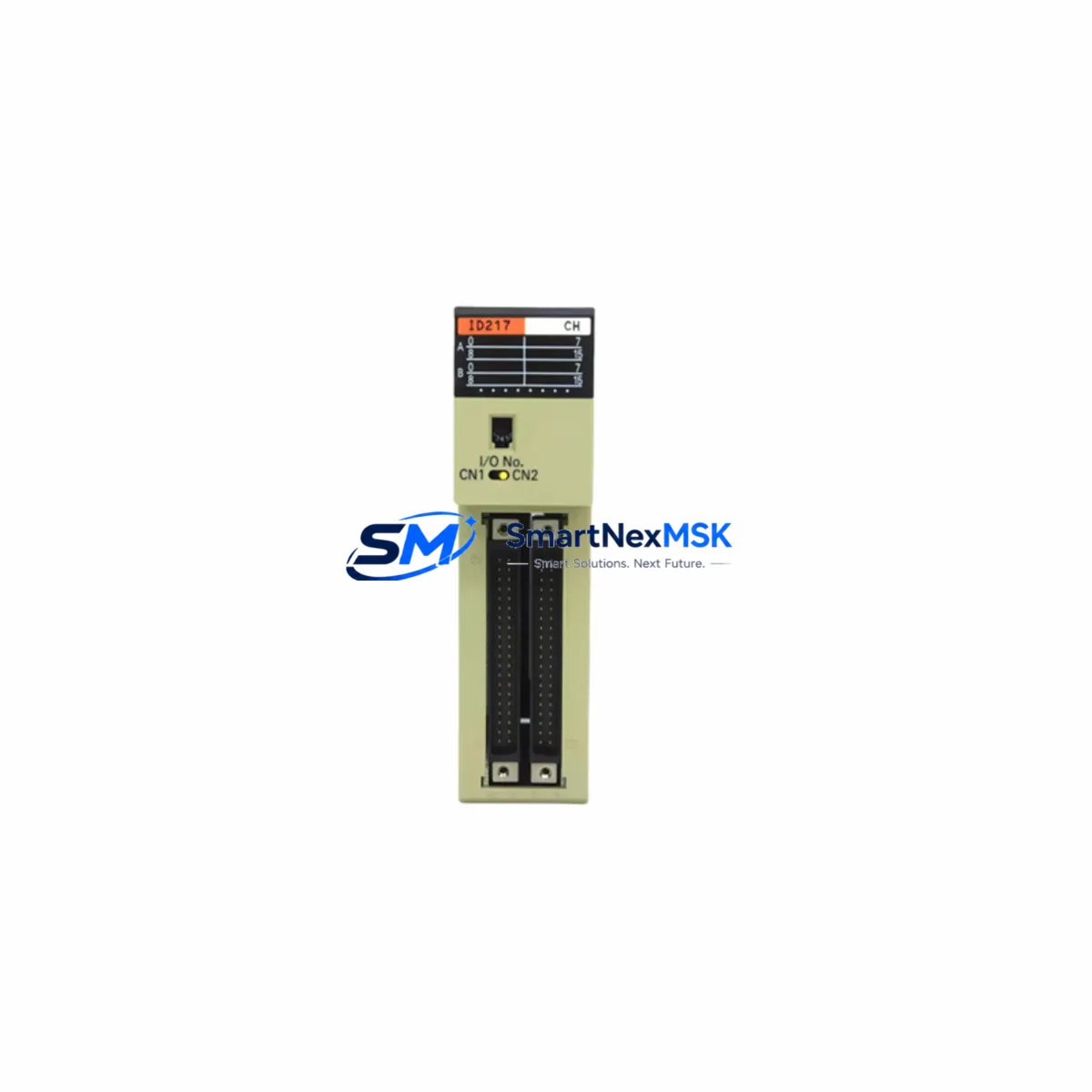
The OMRON SDV-DH7 is a precision voltage sensing relay engineered for seamless integration into existing SDV-DH Series control architectures. Whether you are replacing an end-of-life unit on an aging production line, upgrading a legacy control cabinet, or restoring a system after an unplanned failure, the SDV-DH7 delivers the electrical compatibility, mechanical fit, and operational reliability that industrial engineers demand. With a 12-month warranty and verified pre-shipment testing, this unit is a trusted choice for retrofit projects across power distribution panels, motor control centers, and process automation systems.
Sourced directly from authorized supply channels and stocked for immediate dispatch, the SDV-DH7 is available to customers worldwide. Each unit undergoes functional verification before shipment, ensuring that your replacement arrives ready for installation without additional bench testing delays.
Upgrade Compatibility Table
| Parameter | SDV-DH7 (Replacement) | Notes / Retrofit Guidance |
|---|---|---|
| Series Compatibility | SDV-DH Series | Direct drop-in for SDV-DH family variants |
| Mounting / Installation | DIN Rail / Panel Mount | Verify rail pitch and panel cutout before installation |
| Terminal Wiring | Screw terminal, standard pitch | Match existing wiring diagram; no re-termination required for direct replacements |
| Communication Compatibility | Hardwired relay output | No protocol migration required; integrates with existing PLC I/O modules |
| Replacement Recommendation | 1:1 drop-in replacement for SDV-DH7 | Confirm voltage range and setpoint calibration after swap |
| Commissioning Focus | Voltage threshold setpoint, hysteresis, output relay state | Re-verify setpoints using original engineering drawings |
| Warranty | 12 Months | Covers manufacturing defects; includes pre-shipment functional test |
Retrofit Planning for Existing Automation Systems
Successful integration of the SDV-DH7 into a legacy system requires a structured approach that accounts for the full scope of the control architecture. In most SDV-DH Series installations, the voltage sensing relay operates in close coordination with upstream power supply modules and downstream I/O expansion modules. Before initiating a swap, engineers should audit the power budget of the control cabinet to confirm that the existing OMRON S8VS or equivalent DIN rail power supply can sustain the relay’s operating current without margin violation.
On the I/O side, the SDV-DH7’s relay output typically feeds into a digital input card on the host PLC — commonly an OMRON CJ1W-ID211 or similar CJ-Series input module. Verify that the input card’s voltage threshold and response time are compatible with the relay’s switching characteristics. If the host controller is a OMRON CJ2M CPU or CS1D redundant CPU, confirm that the I/O table and memory allocation in CX-Programmer reflect the correct channel assignment for the replacement unit.
For systems using a OMRON CJ1W-SCU21-V1 serial communication unit or similar protocol bridge, no changes to the communication stack are required, as the SDV-DH7 operates as a hardwired device. However, if the control cabinet also houses a OMRON NX-ECC203 EtherCAT coupler for distributed I/O, ensure that the coupler’s node address and I/O mapping remain undisturbed during the physical swap.
Backplane and rack integrity should also be assessed. In multi-slot configurations using an OMRON CJ1W-BC051 or similar backplane, confirm that adjacent modules — including analog input cards and thermocouple modules — are properly seated and that the bus connector is free of corrosion or mechanical stress before powering the system back on.
HMI screens connected via OMRON NB7W-TW01B or equivalent operator panels should be reviewed to confirm that any alarm or status display linked to the voltage sensing relay’s output bit is correctly mapped. If the original SDV-DH7 was associated with a specific alarm tag in the HMI project, verify that the tag address has not shifted due to any I/O reorganization performed during the retrofit.
Finally, if the system uses a OMRON CX-One programming environment, retain a backup of the original PLC program before any hardware change. This ensures that program logic, function block parameters, and data memory values can be restored immediately if commissioning reveals unexpected behavior.
Downtime Control During System Migration
Minimizing unplanned downtime is the primary operational concern during any voltage relay replacement. For the SDV-DH7, the recommended approach is a hot-standby swap procedure: document the existing setpoint values and wiring configuration before de-energizing the cabinet, then execute the physical replacement within a planned maintenance window. Because the SDV-DH7 is a 1:1 drop-in replacement for the original SDV-DH7 unit, no changes to the PLC program logic are required in standard retrofit scenarios.
To protect original program logic, always upload the current PLC program to a laptop running CX-Programmer or Sysmac Studio before disconnecting any hardware. Store the backup on a local drive and verify the checksum before proceeding. Once the new SDV-DH7 is installed and wired, perform a cold-start sequence and monitor the relay’s output state against the expected voltage threshold before returning the system to automatic mode.
For critical processes where even a brief interruption is unacceptable, consider staging the replacement during a scheduled production break and pre-configuring the new unit on a bench test rig using a variable AC source to confirm setpoint accuracy. This approach reduces in-cabinet commissioning time to under 15 minutes and ensures that field control continuity is maintained throughout the migration.
Retrofit Support FAQ
Q1: Is the SDV-DH7 a direct replacement for the original SDV-DH7 unit?
Yes. The SDV-DH7 is designed as a 1:1 drop-in replacement within the SDV-DH Series. Terminal layout, mounting dimensions, and electrical ratings are consistent with the original specification. Confirm voltage range and setpoint calibration after installation using the original engineering drawings.
Q2: What commissioning steps are required after installation?
After physical installation, re-verify the voltage threshold setpoint and hysteresis values against the original system documentation. Check the relay output state under both normal and fault voltage conditions before returning the system to automatic operation. If the unit is connected to a PLC digital input, confirm the input bit status in the PLC program matches the expected relay state.
Q3: How do I confirm wiring compatibility before installation?
Refer to the original SDV-DH Series wiring diagram and compare terminal assignments with the SDV-DH7 datasheet. In most cases, existing field wiring can be reconnected without modification. Pay particular attention to the common terminal, voltage input terminals, and relay output contacts to avoid miswiring.
Q4: What does the 12-month warranty cover, and is pre-shipment testing performed?
The 12-month warranty covers manufacturing defects and functional failures under normal operating conditions. Every SDV-DH7 unit undergoes a pre-shipment functional test to verify relay operation, setpoint response, and output contact integrity before dispatch. Warranty claims are supported by our technical team with replacement or repair at no additional cost within the warranty period.
© 2026 SMARTNEXMSK. All rights reserved.
Original Source: https://smartnexmsk.com
Contact: [email protected] | +86 18259474341