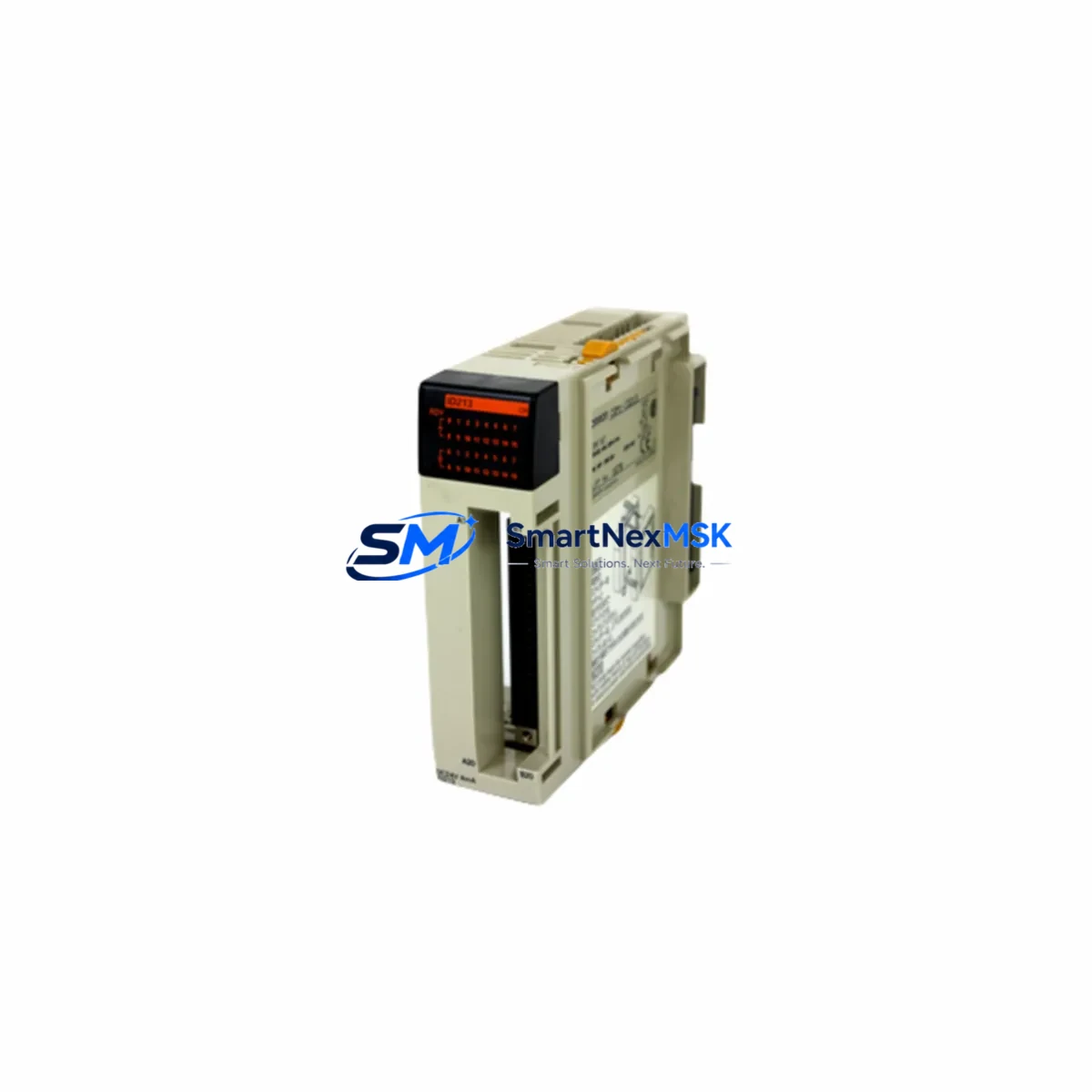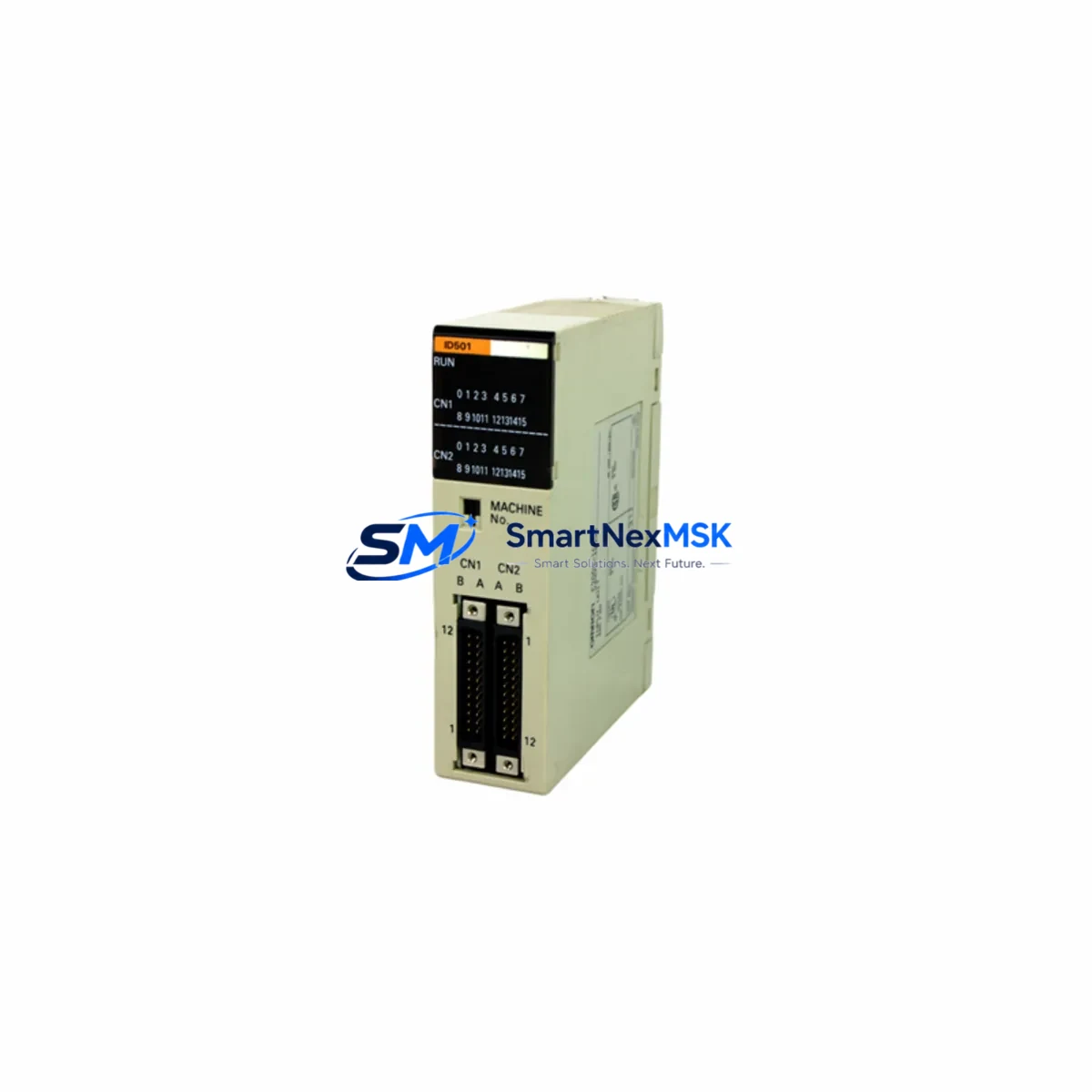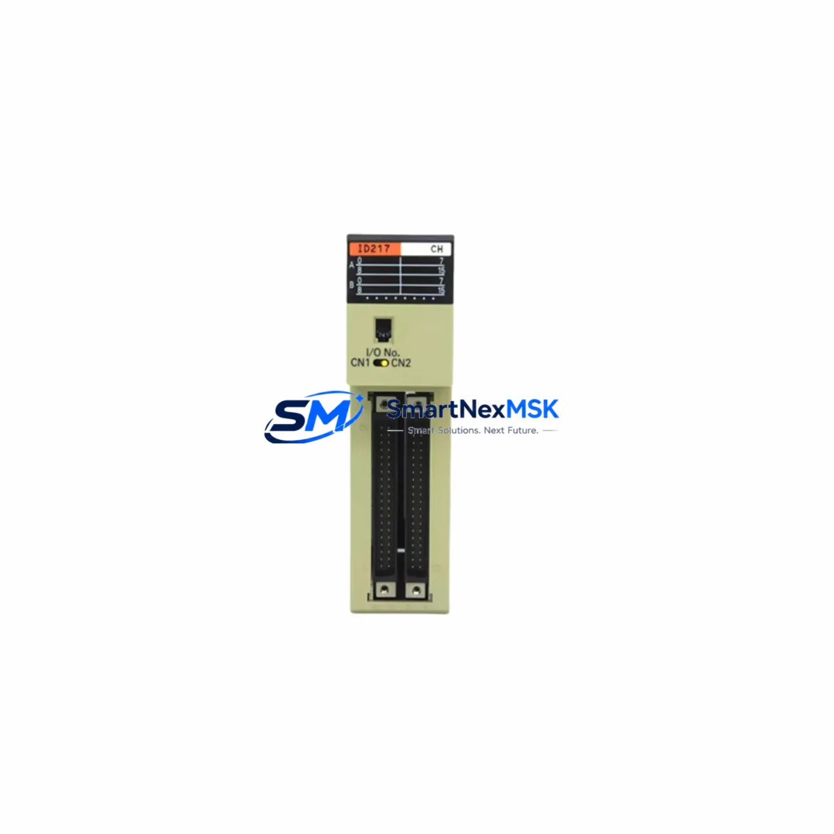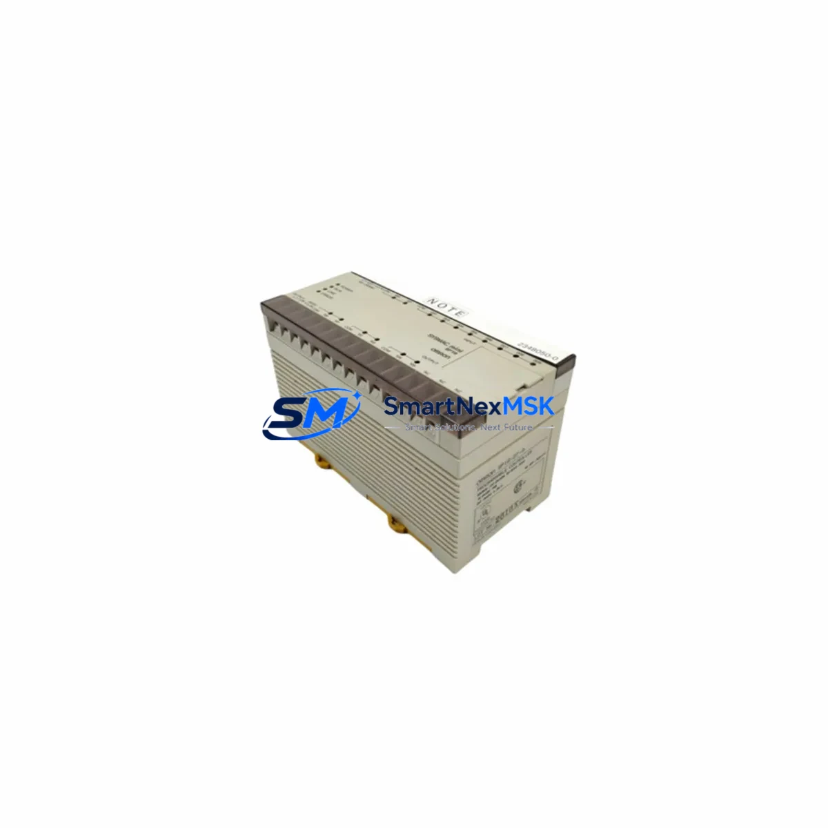
OMRON SP16-DT-A Retrofit-Ready DC Transistor PLC for SysmacSP Control Systems
The OMRON SP16-DT-A is a compact, high-reliability programmable logic controller from the SysmacSP Series, purpose-built for applications where legacy system continuity, minimal downtime, and verified compatibility are non-negotiable. Whether you are replacing a failed unit on an aging production line, upgrading a discontinued control cabinet, or migrating from an older OMRON C-series or CPM-series platform, the SP16-DT-A delivers the I/O density, transistor output performance, and communication flexibility required for a smooth, low-risk retrofit.
With 16 points of DC input and transistor (NPN sink) output, the SP16-DT-A integrates directly into existing SysmacSP backplane configurations without requiring rewiring of field devices. Engineers planning a retrofit must verify the power supply capacity of the existing control cabinet — the SP16-DT-A operates on a 24 VDC supply and draws a defined load that must be accounted for alongside any co-installed modules such as the SP16-ER-A relay output expansion or the SP8-DT-A compact variant. Confirm that the existing DIN-rail mounted power supply, typically a S8VS or S8JX series OMRON PSU, can sustain the combined current draw before commissioning.
Terminal wiring on the SP16-DT-A follows the standard SysmacSP screw-terminal layout. When replacing a unit in the field, technicians should photograph or document the existing wiring before removal, paying particular attention to the 0 V common reference, the 24 V input supply rail, and the transistor output commons. Misidentification of the output common polarity is the most frequent commissioning error during like-for-like replacements. Cross-reference the terminal block pinout against the original panel drawing before energizing.
Backplane interface compatibility is a critical checkpoint. The SP16-DT-A connects to the SysmacSP CPU unit — typically the SP-CPU01-DT or SP-CPU02-DT — via the dedicated expansion connector. Module address assignment is automatic in the SysmacSP architecture, but the physical slot position determines the I/O memory map. If the replacement unit is installed in a different slot than the original, the ladder program must be reviewed and updated accordingly in CX-Programmer or the applicable OMRON programming environment. Failure to reconcile slot addressing is a common source of post-replacement faults.
Program compatibility between the original and replacement SP16-DT-A is generally maintained provided the firmware revision is equivalent or later. Back up the existing program from the CPU — using a CS1W-CN226 or USB-CN226 programming cable — before any hardware swap. Verify that all function blocks, timer presets, counter values, and data memory (DM) contents are preserved in the backup. For systems where the HMI panel — such as an NB7W-TW01B or NS5-SQ11B-V2 — communicates directly with the CPU over RS-232C or RS-485, confirm that the communication parameters (baud rate, data bits, parity, stop bits, station number) are correctly restored after the CPU is restarted with the replacement module installed.
Communication link integrity is especially important in multi-drop or networked installations. If the SP16-DT-A is part of a system using CompoNet, DeviceNet, or SYSMAC LINK — facilitated by a co-installed communications module such as the CS1W-CLK21 or a dedicated gateway — verify that the node address and baud rate settings are re-established after replacement. Network topology changes introduced during a retrofit, such as adding a new I/O node or rerouting a trunk cable, must be reflected in the network configuration tool before the system is returned to automatic operation.
For I/O expansion requirements beyond the base 16 points, the SP16-DT-A supports connection of additional SysmacSP expansion units. Common expansion choices in retrofit projects include the SP16-ER-A for relay output applications involving higher-voltage loads, and analog I/O modules where process variable monitoring is required. Confirm the maximum expansion unit count supported by the specific CPU variant in use, as exceeding this limit will result in a configuration error at startup.
All SP16-DT-A units supplied by SMARTNEXMSK are subject to pre-shipment functional testing, including power-on verification, I/O point actuation checks, and communication port validation. Each unit ships with a 12-month warranty covering manufacturing defects and functional failures under normal operating conditions. Units are sourced from verified supply channels and are accompanied by documentation confirming authenticity. Stock availability is maintained to support urgent replacement requirements, with expedited dispatch available for critical production downtime situations.
Upgrade Compatibility Table
| Parameter | SP16-DT-A (This Unit) | Retrofit / Replacement Notes |
|---|---|---|
| I/O Points | 16 (8 DC In / 8 Transistor Out) | Direct replacement for same-spec SysmacSP units; verify slot position for I/O mapping |
| Output Type | Transistor (NPN Sink) | Not interchangeable with relay output variants (SP16-ER-A); confirm load type before swap |
| Supply Voltage | 24 VDC | Verify existing PSU capacity (S8VS / S8JX series recommended); check combined module draw |
| Backplane Interface | SysmacSP Expansion Connector | Compatible with SP-CPU01-DT / SP-CPU02-DT; slot position determines I/O memory address |
| Programming Environment | CX-Programmer (OMRON) | Back up program via CS1W-CN226 / USB-CN226 cable before replacement |
| HMI Communication | RS-232C / RS-485 | Restore comm parameters (baud, parity, station no.) after CPU restart; compatible with NB/NS series HMI |
| Network Protocols | CompoNet / DeviceNet / SYSMAC LINK | Re-establish node address and baud rate after replacement; update network config tool |
| Installation | DIN Rail / Panel Mount | Standard SysmacSP mechanical footprint; no panel modification required for like-for-like swap |
| Warranty | 12 Months | Covers manufacturing defects and functional failures; pre-shipment tested |
Retrofit Planning for Existing Automation Systems
A successful SP16-DT-A retrofit begins with a thorough audit of the existing control cabinet. Start by identifying all modules currently installed on the SysmacSP backplane or expansion rack: the CPU unit (SP-CPU01-DT or SP-CPU02-DT), any co-installed SP16-ER-A relay output modules, SP8-DT-A compact I/O units, and any analog expansion modules. Document the physical slot order, as this directly determines the I/O memory allocation in the running program.
Next, audit the power distribution within the cabinet. The 24 VDC rail supplying the SP16-DT-A must have sufficient headroom after accounting for all connected field devices — sensors, solenoids, indicator lamps — wired to the input and output terminals. If the existing S8VS or S8JX power supply is operating near its rated current limit, a higher-capacity unit should be specified as part of the retrofit scope before the new module is installed.
For systems that include a communication gateway or protocol converter — for example, a unit bridging SYSMAC LINK to Modbus RTU for integration with a SCADA or DCS layer — the gateway configuration must be reviewed and preserved. Any changes to the PLC node address or communication port settings during the retrofit will require corresponding updates in the gateway parameter file. This is particularly relevant in installations where the SP16-DT-A feeds process data to a higher-level system via an NS5-SQ11B-V2 HMI acting as a data concentrator, or where a dedicated CS1W-CLK21 SYSMAC LINK unit manages inter-PLC communication across multiple control panels.
Programming cable availability is a practical prerequisite that is frequently overlooked. Confirm that a compatible USB-CN226 or CS1W-CN226 cable is on-site before the maintenance window begins. Without the ability to upload and verify the program post-replacement, the retrofit cannot be safely completed. If the original program source file is unavailable, the existing program must be uploaded from the CPU before the old module is removed.
Downtime Control During System Migration
Minimizing production downtime during an SP16-DT-A replacement requires preparation that begins well before the maintenance window. The following approach has been validated across multiple SysmacSP retrofit projects:
Pre-shutdown preparation: Upload and verify the complete program from the existing CPU using CX-Programmer. Save the program file, I/O comments, and symbol table to a secure location. Record all current DM (data memory) values, particularly any recipe parameters, setpoints, or counters that are not reset on power cycle. Photograph all terminal wiring on the SP16-DT-A and any adjacent expansion modules.
During the maintenance window: Power down the control cabinet in the correct sequence — field devices first, then the PLC power supply. Remove the SP16-DT-A from its slot, noting the exact position. Install the replacement unit in the same slot. Reconnect all terminal wiring, verifying each connection against the documented wiring photograph. Restore power to the PLC before reconnecting field devices, and confirm that the CPU recognizes the new module without a configuration error.
Post-replacement verification: Download the saved program to the CPU and perform a forced I/O test on each input and output point before returning the system to automatic mode. Verify HMI communication by confirming that all screen data refreshes correctly and that any alarm or status indicators reflect the actual field state. If the system uses a network protocol such as CompoNet or DeviceNet, confirm that all nodes are online and communicating before releasing the line.
With proper preparation, a like-for-like SP16-DT-A replacement can typically be completed within a two-hour maintenance window, preserving original program logic and maintaining field control continuity throughout the process.
Retrofit Support FAQ
Q: Is the SP16-DT-A a direct drop-in replacement for my existing SysmacSP module?
A: Yes, provided the existing module is also a transistor (NPN) output variant installed in the same backplane slot. If the original module was a relay output type (SP16-ER-A), the SP16-DT-A is not a direct electrical substitute — output wiring and load compatibility must be re-evaluated. Confirm the output type from the original module label or panel drawing before ordering.
Q: What pre-shipment testing is performed on each SP16-DT-A unit?
A: Every unit undergoes power-on verification, individual I/O point actuation testing, and communication port validation before dispatch. Units that do not pass all test criteria are not shipped. A 12-month warranty covering manufacturing defects and functional failures is included with each unit.
Q: Do I need to modify my existing ladder program after installing the replacement SP16-DT-A?
A: If the replacement unit is installed in the same physical slot as the original, no program changes are required — the I/O memory mapping is preserved. If the slot position changes for any reason, the I/O addresses referenced in the ladder program must be updated in CX-Programmer to reflect the new slot assignment before the system is returned to automatic operation.
Q: Can the SP16-DT-A be used in a system that also includes older OMRON CPM or C-series controllers?
A: The SP16-DT-A is a SysmacSP Series module and is not mechanically or electrically compatible with CPM1A, CPM2A, or C200H backplanes. However, it can coexist in the same control cabinet as CPM or C-series controllers as a standalone unit, provided it is connected to a compatible SysmacSP CPU. Protocol-level integration between SysmacSP and C-series platforms is possible via RS-232C or a dedicated communications module, but requires custom configuration in CX-Programmer.
© 2026 SMARTNEXMSK. All rights reserved.
Original Source: https://smartnexmsk.com
Contact: [email protected] | +86 18259474341