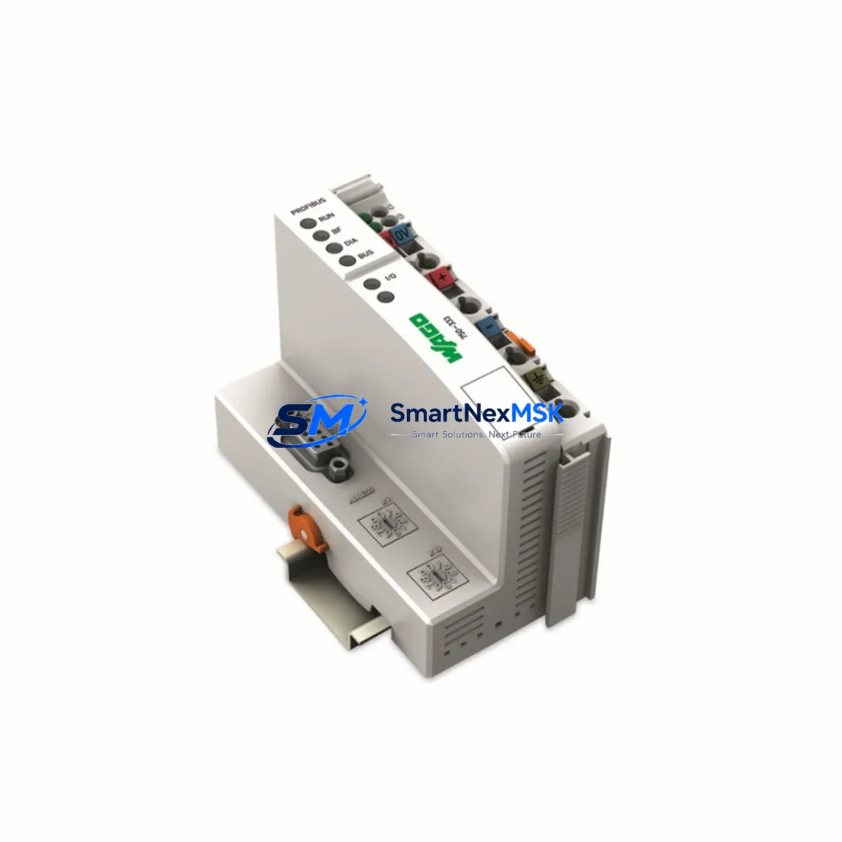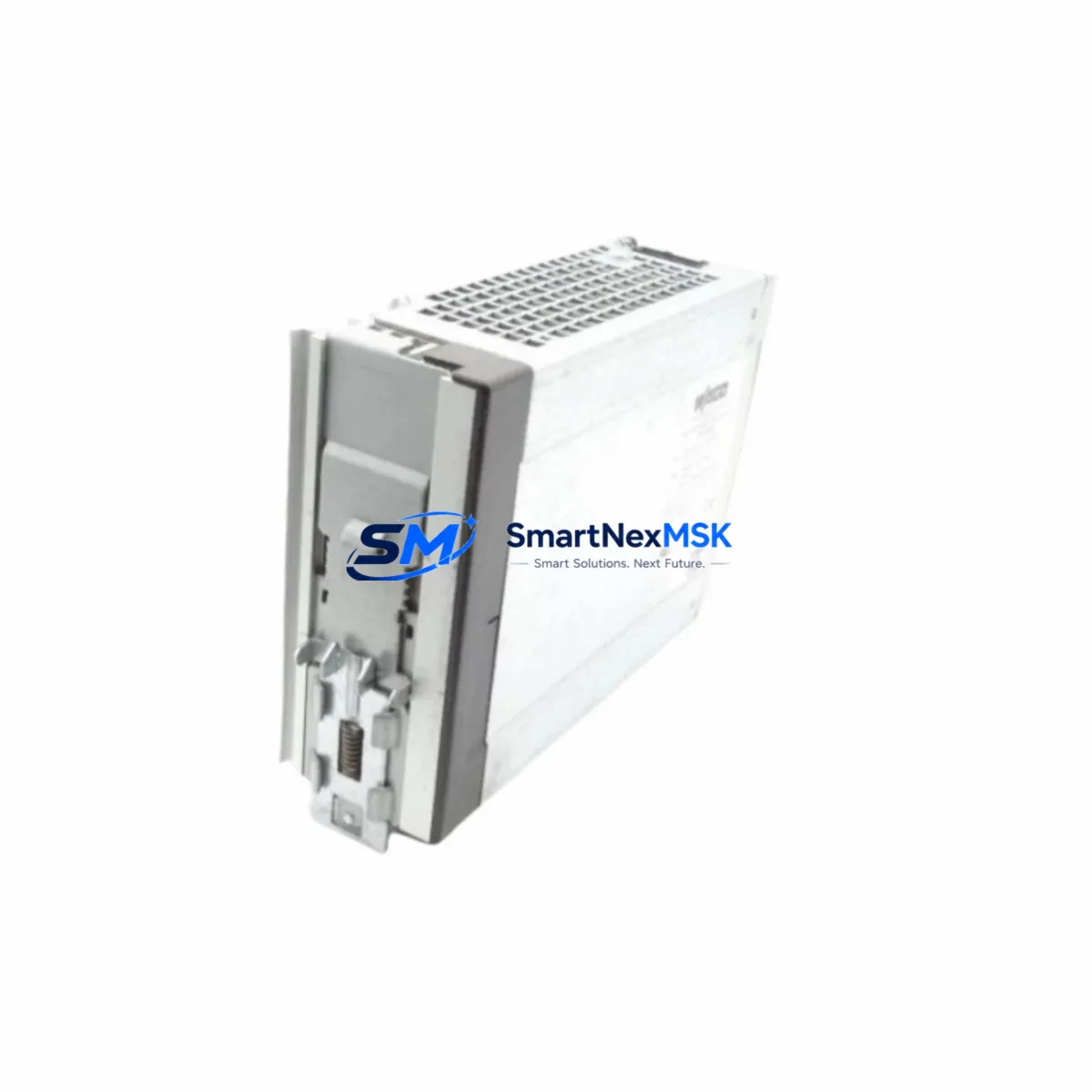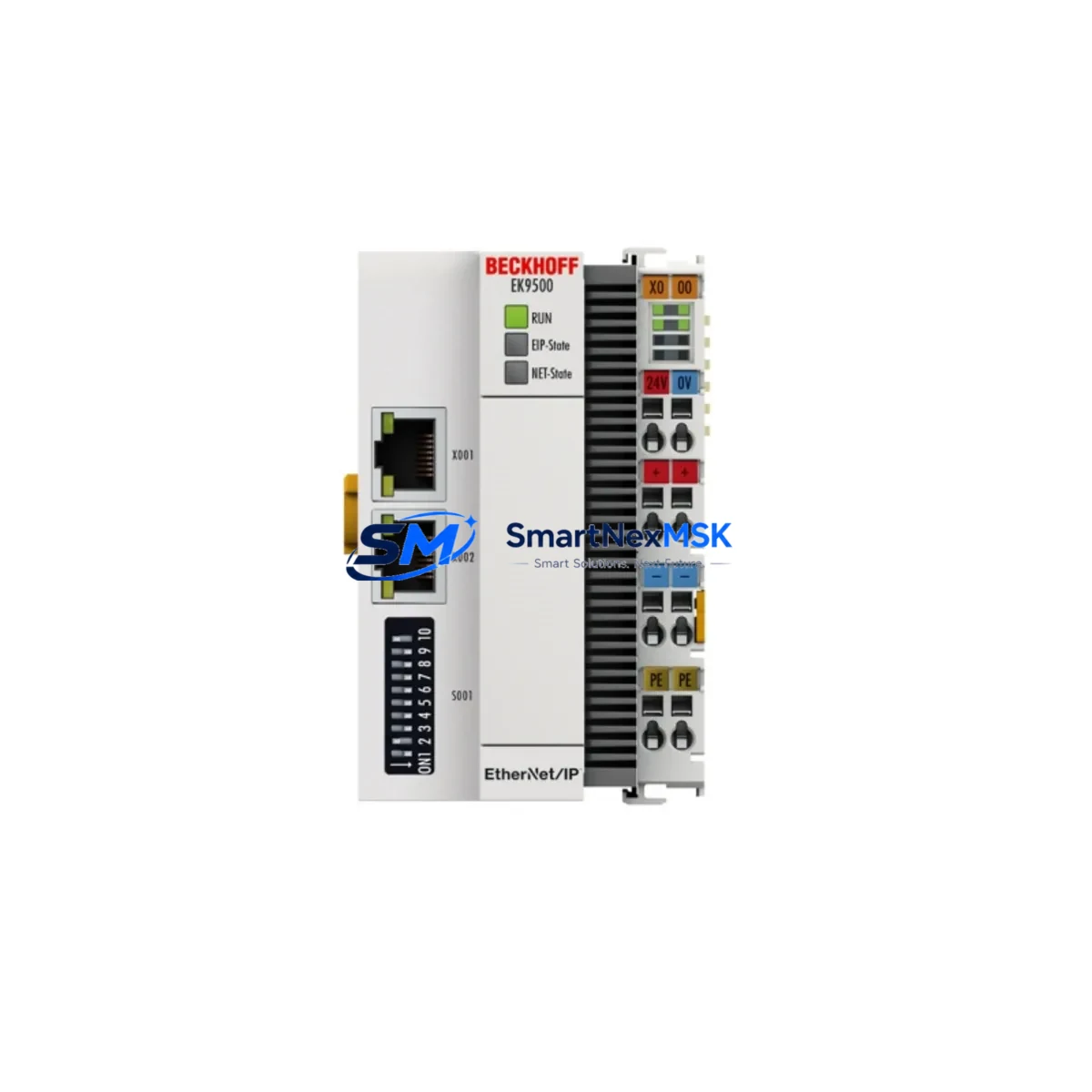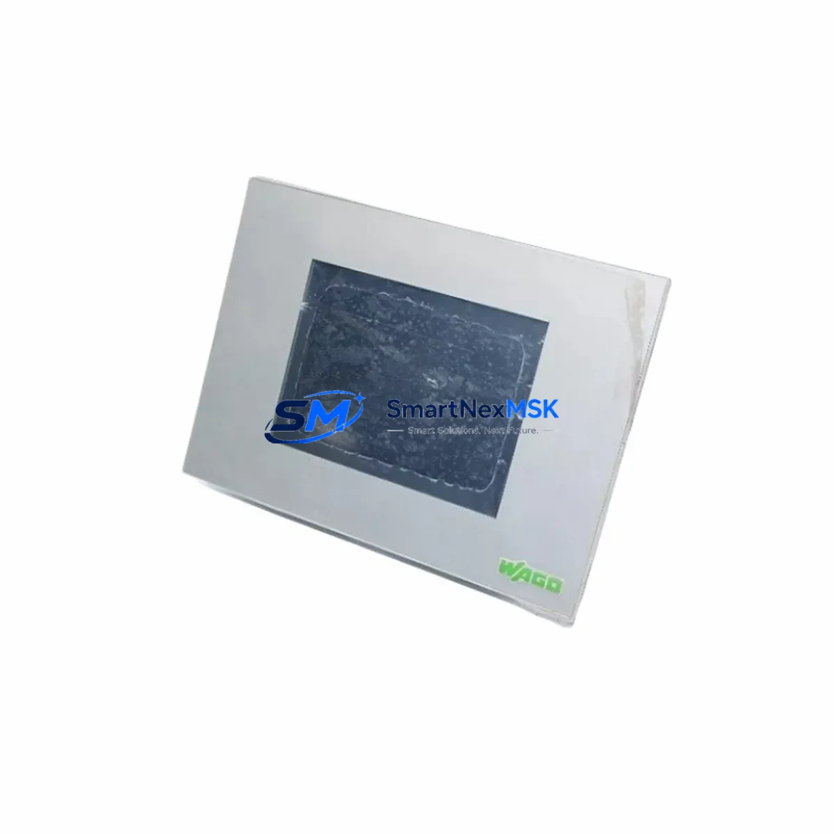
WAGO 0762-3057/0001-0000 Retrofit-Ready I/O Module for 750/760 Series Control Systems
The WAGO 0762-3057/0001-0000 is a high-reliability I/O control panel module engineered for seamless integration into WAGO 750/760 Series fieldbus-based control architectures. Designed with retrofit and system modernization in mind, this module serves as a direct functional replacement for discontinued or end-of-life variants within the 750/760 platform, enabling engineers to restore full system capability without redesigning the control cabinet or rewriting PLC logic from scratch.
Whether you are upgrading an aging production line, recovering from an unplanned module failure, or executing a planned migration from legacy WAGO hardware, the 0762-3057/0001-0000 delivers the electrical compatibility, mechanical fit, and communication protocol alignment required for a smooth, low-risk transition. Its DIN-rail mounting footprint matches the standard 750 Series node spacing, and its terminal wiring layout is consistent with predecessor modules, significantly reducing field rewiring time during replacement.
Upgrade Compatibility Table
| Parameter | Details |
|---|---|
| Compatible Series | WAGO 750 Series, WAGO 760 Series fieldbus nodes |
| Backplane Interface | WAGO internal data bus; compatible with 750-300, 750-400, 750-800 coupler families |
| Communication Protocols | PROFIBUS DP, CANopen, DeviceNet, Modbus RTU/TCP (coupler-dependent) |
| Terminal Wiring | CAGE CLAMP® spring-clamp terminals; tool-free, vibration-resistant |
| Installation Requirement | 35 mm DIN rail; standard 750/760 node slot; no adapter required |
| Replacement Recommendation | Direct drop-in for compatible 750/760 I/O modules; verify module address in PLC program |
| Commissioning Notes | Confirm I/O address mapping in WAGO-I/O-PRO or e!COCKPIT; update GSD/EDS file if required |
| Power Supply Compatibility | 24 VDC system bus; verify field-side supply capacity before installation |
| Warranty | 12-Month Warranty — covers manufacturing defects and functional failure under normal operating conditions |
Retrofit Planning for Existing Automation Systems
Successful integration of the WAGO 0762-3057/0001-0000 into an existing control system begins with a thorough audit of the current node configuration. Engineers should document the full rack layout, including the WAGO 750-352 or 750-342 fieldbus coupler at the head of the node, all adjacent I/O modules, and the end module — typically a WAGO 750-600 — that terminates the internal data bus. This baseline inventory ensures that the replacement module is inserted at the correct slot position and that the PLC program’s I/O address table remains consistent after the swap.
Power budget verification is a critical pre-installation step. The 750/760 Series internal bus operates at 5 VDC supplied by the coupler, while field-side circuits typically run at 24 VDC. Before installing the 0762-3057/0001-0000, calculate the cumulative current draw of all modules on the node to confirm the coupler’s internal bus current capacity is not exceeded. If the existing system uses a WAGO 750-613 or 750-614 power supply module to segment the node, ensure the new module falls within the correct power segment.
For systems communicating over PROFIBUS DP, the GSD file associated with the node configuration must be reviewed in the PROFIBUS master — such as a Siemens S7-300/400 or S7-1500 hardware configuration — to confirm the module slot assignment matches the physical installation. In CANopen networks, the EDS file and node object dictionary should be verified using a CANopen configuration tool before going live. Where the legacy system used Modbus RTU over RS-485 via a WAGO 750-315 or 750-316 coupler, the register map should be validated against the new module’s I/O channel count to prevent address conflicts.
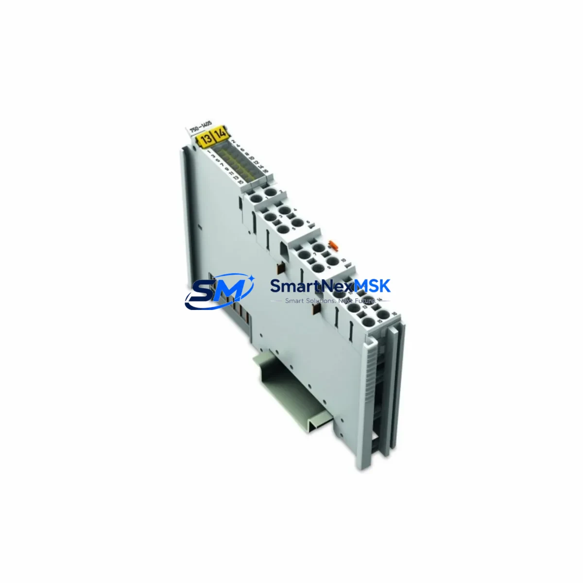
Terminal wiring adaptation is straightforward due to WAGO’s consistent CAGE CLAMP® connector design across the 750/760 range. However, engineers should cross-reference the original wiring diagram against the 0762-3057/0001-0000 datasheet to confirm signal polarity, channel grouping, and any differences in common terminal arrangement. If the legacy module used a different channel density, field wiring may need to be redistributed across an additional WAGO 750-1405 or 750-1515 digital input module to maintain full I/O coverage.
HMI screen updates are often overlooked during module replacements. If the control system includes a WAGO Touch Panel or a third-party HMI communicating via OPC UA or Modbus TCP, verify that all tag addresses referencing the replaced module’s channels are still valid after the swap. A mismatch between the HMI tag database and the updated PLC I/O table can cause silent data errors or alarm suppression that only surfaces during production.
Programming cable access is required if the PLC program needs to be modified during commissioning. Ensure a WAGO 750-923 programming cable or equivalent USB-to-serial adapter is available on-site, along with a laptop loaded with WAGO-I/O-PRO 32 or e!COCKPIT, to allow real-time monitoring of I/O status and online program adjustments without a full system restart.
Downtime Control During System Migration
Minimizing unplanned downtime is the primary concern when replacing I/O modules in a live production environment. The recommended approach for the WAGO 0762-3057/0001-0000 retrofit is a hot-swap preparation strategy: pre-configure and bench-test the replacement module offline before the scheduled maintenance window. Using a spare WAGO 750-352 coupler and a laptop with e!COCKPIT, simulate the target node configuration and verify that the module responds correctly to test signals before it is installed in the field.
During the actual replacement, follow a structured sequence: power down the field-side 24 VDC supply first, then remove the defective module from the DIN rail without disturbing adjacent modules or their wiring. Insert the 0762-3057/0001-0000, reconnect field wiring using the original terminal documentation, and restore field power before re-enabling the fieldbus coupler. This sequence protects the internal data bus from transient faults and prevents the PLC from logging spurious I/O errors during the swap.
To preserve original program logic, export a full backup of the PLC project from WAGO-I/O-PRO or e!COCKPIT before beginning any hardware changes. If the system uses a WAGO 750-881 or 750-882 controller with onboard program storage, verify that the project backup includes the current variable table and I/O configuration. After the module is installed and powered, perform a forced I/O test on each channel of the 0762-3057/0001-0000 to confirm correct signal routing before releasing the system back to automatic control.
For critical processes where even a brief interruption is unacceptable, consider a parallel commissioning approach: install the new module in a shadow slot on an adjacent test node, validate all I/O channels against live field signals using a WAGO 750-627 or 750-628 potential distribution module to share field wiring, and only cut over to the new module after full validation. This approach keeps the original module active until the last possible moment, reducing the risk of extended downtime due to unexpected commissioning issues.
All replacement units supplied by SMARTNEXMSK undergo pre-shipment functional testing to verify channel integrity, bus communication, and terminal continuity. Each 0762-3057/0001-0000 is covered by a 12-month warranty from the date of shipment, providing assurance against manufacturing defects and functional failure under normal industrial operating conditions.
Retrofit Support FAQ
Q1: Is the WAGO 0762-3057/0001-0000 a direct drop-in replacement for other 750/760 Series I/O modules?
A: The 0762-3057/0001-0000 is functionally compatible with the WAGO 750/760 Series internal data bus and shares the same DIN-rail footprint and CAGE CLAMP® terminal design. However, channel count, signal type, and I/O address mapping must be verified against the original module’s datasheet and the PLC program before installation. In most cases, no hardware modification to the control cabinet is required.
Q2: What commissioning steps are required after installing the replacement module?
A: After physical installation, power up the node and use WAGO-I/O-PRO or e!COCKPIT to confirm the module is recognized on the internal bus. Perform a forced I/O test on each channel, verify the fieldbus master (PROFIBUS, CANopen, or Modbus) is reading correct data, and check HMI tag values against expected field signals. Update the GSD or EDS file in the fieldbus master configuration tool if the module type has changed.
Q3: Can this module be used in systems with mixed WAGO 750 and 760 Series nodes?
A: Yes. The 0762-3057/0001-0000 is compatible with both 750 and 760 Series node architectures, provided the fieldbus coupler at the head of the node supports the module type. Always verify the coupler’s module compatibility list and confirm that the total internal bus current budget is not exceeded when adding the new module to an existing mixed node.
Q4: What does the 12-month warranty cover, and how is it claimed?
A: The 12-month warranty covers manufacturing defects and functional failure under normal industrial operating conditions from the date of shipment. It does not cover damage caused by incorrect installation, overvoltage, reverse polarity, or physical impact. To initiate a warranty claim, contact SMARTNEXMSK at [email protected] with your order number, a description of the fault, and photographic evidence of the defect. Replacement or repair will be arranged within the warranty period.
© 2026 SMARTNEXMSK. All rights reserved.
Original Source: https://smartnexmsk.com
Contact: [email protected] | +86 18259474341