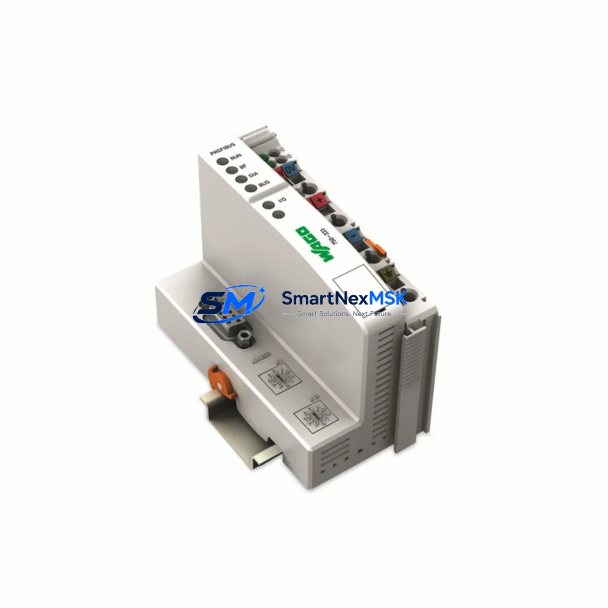
WAGO 750-333 Retrofit-Ready INTERBUS Coupler for 750 Series Control Systems
The WAGO 750-333 is an INTERBUS fieldbus coupler designed for seamless integration into WAGO 750 Series modular I/O systems. As legacy INTERBUS networks age and original couplers reach end-of-life, the 750-333 serves as a proven retrofit-ready replacement that preserves existing wiring infrastructure, DIN-rail mounting geometry, and node addressing logic — minimizing engineering rework and unplanned downtime during control system modernization projects.
Whether you are replacing a failed coupler on an active production line, upgrading a distributed I/O rack in a legacy control cabinet, or migrating a multi-node INTERBUS segment to a more maintainable architecture, the 750-333 provides the electrical and mechanical compatibility required for a controlled, low-risk transition. Its 24 VDC supply input, standard WAGO CAGE CLAMP terminal wiring, and INTERBUS remote bus interface make it directly interchangeable with earlier-generation couplers in the same 750 Series family.
Upgrade Compatibility Table
| Parameter | Details |
|---|---|
| SKU / Part Number | 750-333 |
| Brand / Manufacturer | WAGO |
| Compatible Series | WAGO 750 Series Modular I/O |
| Fieldbus Protocol | INTERBUS (Remote Bus) |
| Supply Voltage | 24 VDC (via system bus) |
| Mounting | DIN-Rail (35 mm), direct backplane snap-fit |
| Terminal Wiring | WAGO CAGE CLAMP — compatible with existing field wiring |
| Backplane Interface | 750 Series internal data/power bus |
| Node Addressing | INTERBUS segment addressing — retains original node ID |
| Replacement Compatibility | Drop-in for earlier 750 Series INTERBUS couplers |
| Installation Requirement | No special tools; standard WAGO assembly sequence |
| Communication Compatibility | INTERBUS-S, INTERBUS Loop compatible segments |
| Retrofit Recommendation | Verify segment length, node count, and power budget before swap |
| Commissioning Notes | Re-scan bus topology in host PLC after replacement; verify I/O mapping |
| Warranty | 12 Months — covers manufacturing defects and functional failure |
| Origin | Germany |
Retrofit Planning for Existing Automation Systems
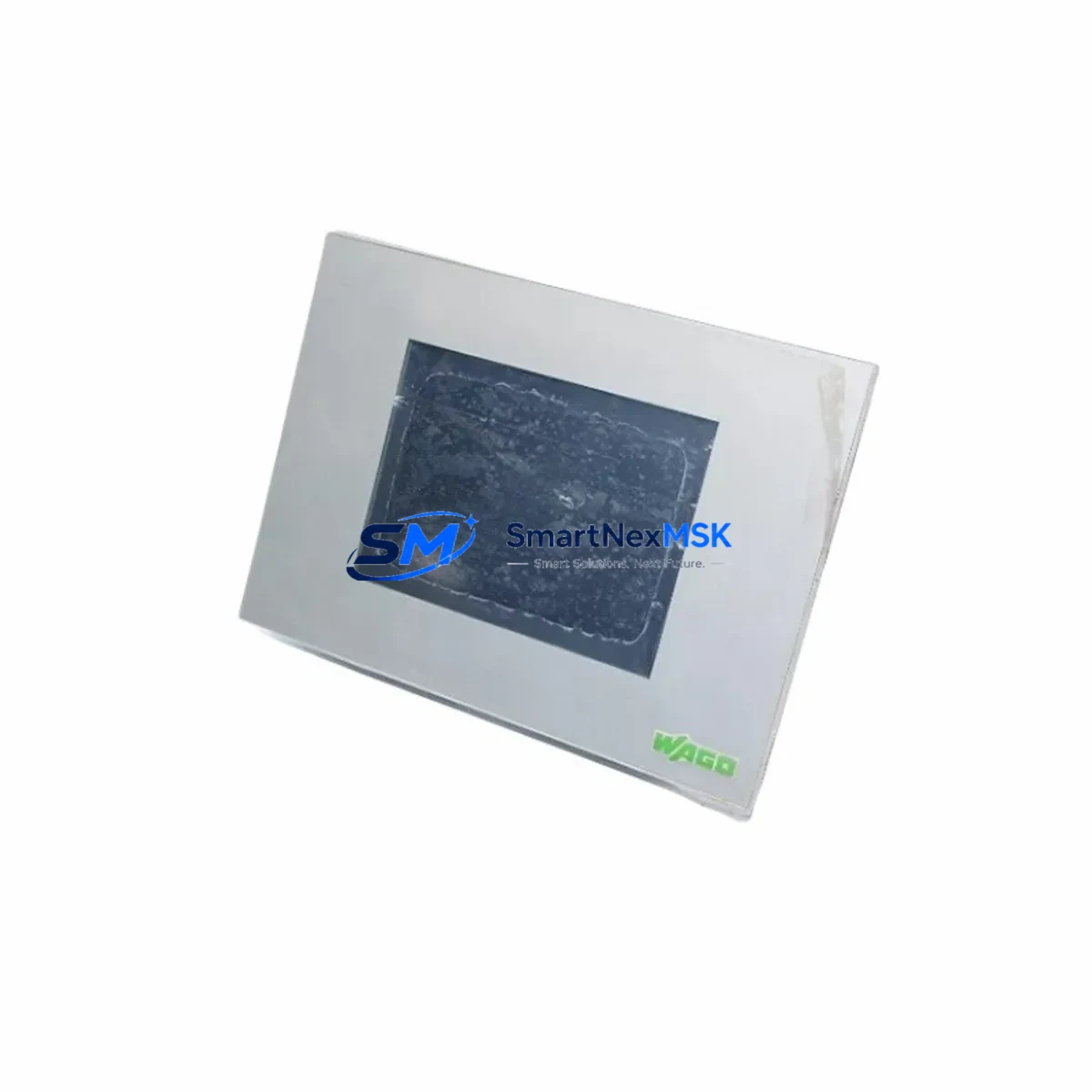
A successful retrofit using the WAGO 750-333 begins with a thorough audit of the existing I/O rack configuration. In a typical 750 Series node, the coupler sits at the head of a backplane assembly that may include digital input modules such as the 750-400 or 750-408, digital output modules such as the 750-501 or 750-504, and analog I/O modules such as the 750-452 or 750-554. Before removing the original coupler, document the physical slot order of every module in the rack — this sequence directly maps to the process image in the host PLC program.
Power supply sizing is a critical pre-retrofit check. The 750-333 draws its logic power from the 750 Series internal bus, but field-side power for output modules is supplied separately. Confirm that the existing 24 VDC field power supply — often a WAGO 787-series or equivalent DIN-rail PSU — can sustain the combined load of all output modules in the node after the coupler swap. If the original coupler included a power jumper module such as the 750-600, verify it remains in the correct slot position after reinstallation.
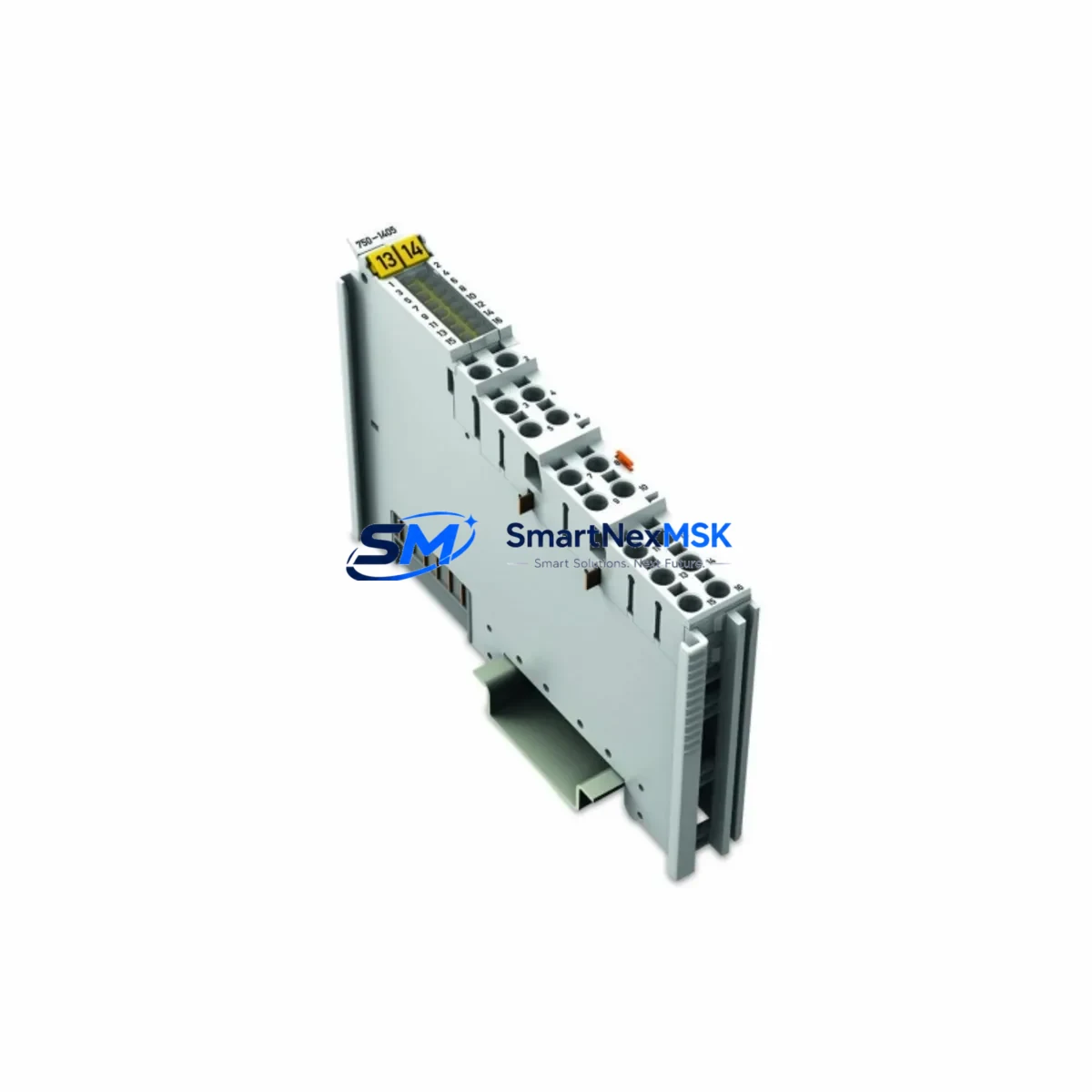
Terminal wiring on the 750-333 uses WAGO’s CAGE CLAMP technology, which is tool-free and compatible with conductors from 0.08 mm² to 2.5 mm². In most retrofit scenarios, existing field cables can be reconnected directly without re-termination, provided conductor cross-sections are within specification. Label each terminal before disconnection to prevent wiring errors during reassembly.
On the INTERBUS side, the 750-333 connects to the remote bus via the standard INTERBUS D-Sub connector. Verify the incoming and outgoing remote bus cables — typically shielded twisted-pair — are undamaged and that the segment termination resistor is correctly placed at the last node in the chain. If the retrofit involves extending the segment or adding new nodes, recalculate the total segment length against the INTERBUS specification to avoid signal integrity issues.
HMI screens referencing I/O tags mapped to this node should be reviewed after the coupler replacement. If the host controller is a Phoenix Contact ILC or similar INTERBUS master, re-scan the bus configuration and confirm that the process data length reported by the 750-333 node matches the original. Any mismatch will require a program adjustment before the system can return to automatic mode. For systems using a WAGO 750-841 or 750-880 controller as the INTERBUS master, the bus configuration is stored in the controller project — update and reload the project if the node data structure changes.
Where the retrofit is part of a broader migration from INTERBUS to PROFIBUS DP or EtherNet/IP, the 750-333 can serve as an interim solution while the new fieldbus infrastructure is commissioned in parallel. In this scenario, the 750-333 maintains production continuity on the INTERBUS segment while new 750-352 (PROFIBUS DP) or 750-342 (DeviceNet) couplers are staged and tested on a bench rack before cutover.
Downtime Control During System Migration
Minimizing production downtime during a coupler replacement requires preparation before the maintenance window opens. The recommended approach is to pre-configure a spare 750-333 on a bench rack, verify its behavior with a representative I/O module set, and confirm that the INTERBUS master recognizes the node correctly before scheduling the live swap.
During the swap, the sequence is: power down the field supply to the affected node, disconnect the INTERBUS remote bus cables (noting IN and OUT orientation), remove the original coupler from the DIN rail, install the 750-333, reconnect the remote bus cables in the correct orientation, and restore field power. The entire physical swap typically takes under 15 minutes for a trained technician familiar with the 750 Series assembly system.
After power restoration, the INTERBUS master will perform an automatic bus scan. If the host PLC is running a Phoenix Contact PC WORX or WAGO e!COCKPIT project, verify that the detected node configuration matches the stored project configuration before releasing the system to automatic control. If the I/O module lineup in the rack has not changed, the program logic, HMI tag bindings, and communication links will resume without modification. Keep the original coupler as a tested spare to further reduce recovery time in future fault scenarios.
For critical processes where even a brief interruption is unacceptable, consider a hot-standby approach: install a parallel I/O node with a second 750-333 on a separate INTERBUS segment, validate its outputs against the primary node in shadow mode, then perform a controlled switchover during a scheduled low-production period. This approach is particularly effective in continuous-process industries such as chemical dosing, water treatment, and food processing where control continuity is a safety requirement.
Retrofit Support FAQ
Q1: Is the WAGO 750-333 a direct drop-in replacement for my existing INTERBUS coupler in a 750 Series rack?
In most cases, yes. The 750-333 uses the same DIN-rail footprint, CAGE CLAMP terminal wiring, and 750 Series backplane interface as earlier INTERBUS couplers in the same family. Confirm the INTERBUS protocol variant (INTERBUS-S vs. INTERBUS Loop) and the remote bus connector pinout before installation. No mechanical modification to the cabinet or rack is required in standard retrofit scenarios.
Q2: Do I need to modify my PLC program after replacing the coupler?
If the I/O module lineup in the rack remains unchanged and the node address is preserved, the existing PLC program, I/O mapping, and HMI tag assignments will continue to function without modification. A bus re-scan in the INTERBUS master is required after the swap to confirm the node is recognized. Program changes are only necessary if the process data length or module configuration differs from the original.
Q3: What commissioning checks should I perform after installation?
After installing the 750-333, verify: (1) INTERBUS master detects the node and reports correct process data length; (2) all I/O modules in the rack are recognized and their status LEDs indicate normal operation; (3) field wiring continuity is confirmed for all terminal connections; (4) HMI displays update correctly for all I/O points mapped to this node; (5) any interlocks or safety functions associated with this node are tested before returning to automatic mode.
Q4: What does the 12-month warranty cover?
The 12-month warranty covers manufacturing defects and functional failure under normal operating conditions. Each unit undergoes pre-shipment functional testing to verify INTERBUS communication, backplane interface integrity, and terminal wiring continuity. Warranty claims are supported by SMARTNEXMSK’s technical team — contact [email protected] with your order reference and a description of the fault for rapid resolution.
© 2026 SMARTNEXMSK. All rights reserved.
Original Source: https://smartnexmsk.com
Contact: [email protected] | +86 18259474341