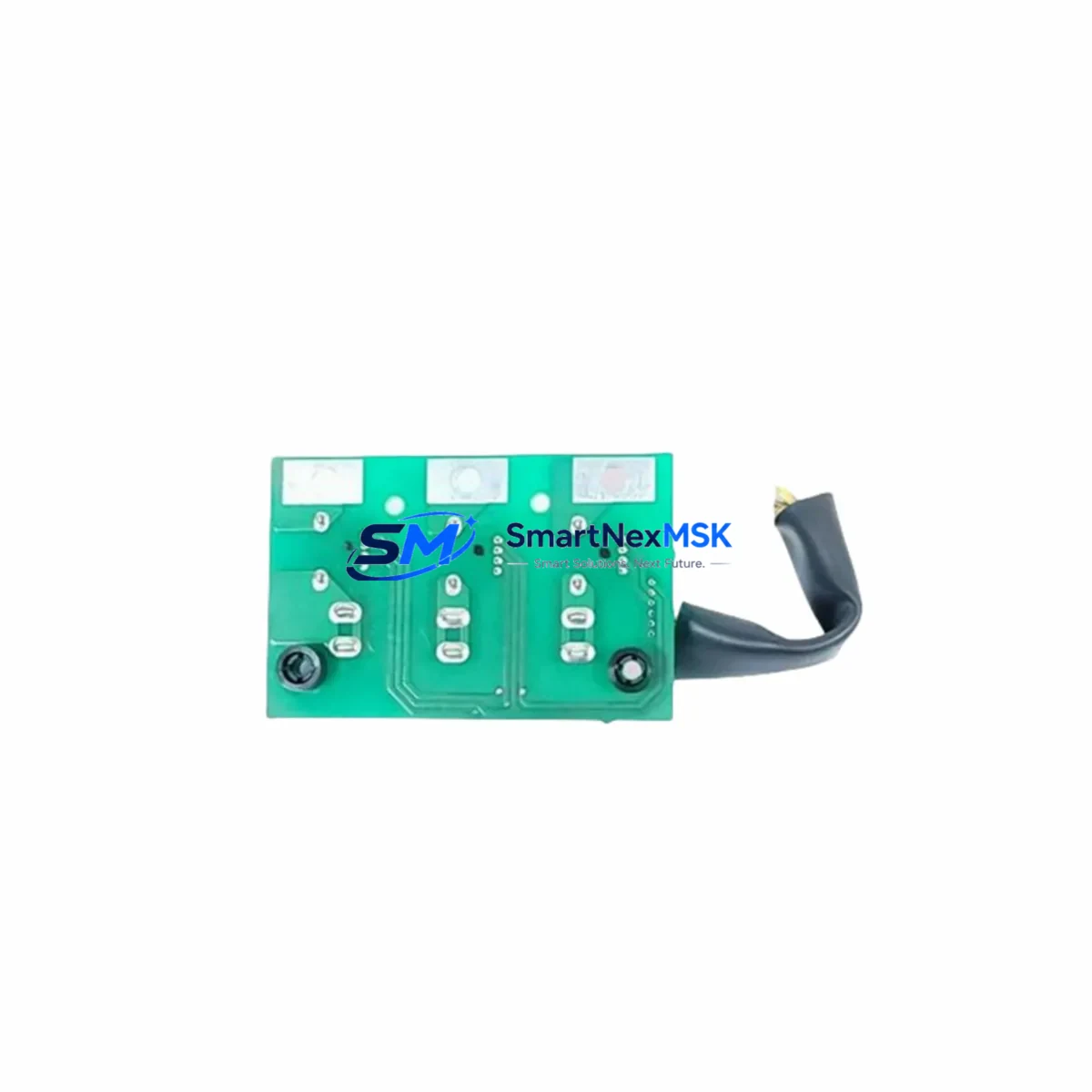
YASKAWA DESIG 3PCB YWP-EF Maintenance-Ready Spare for YWP Automation
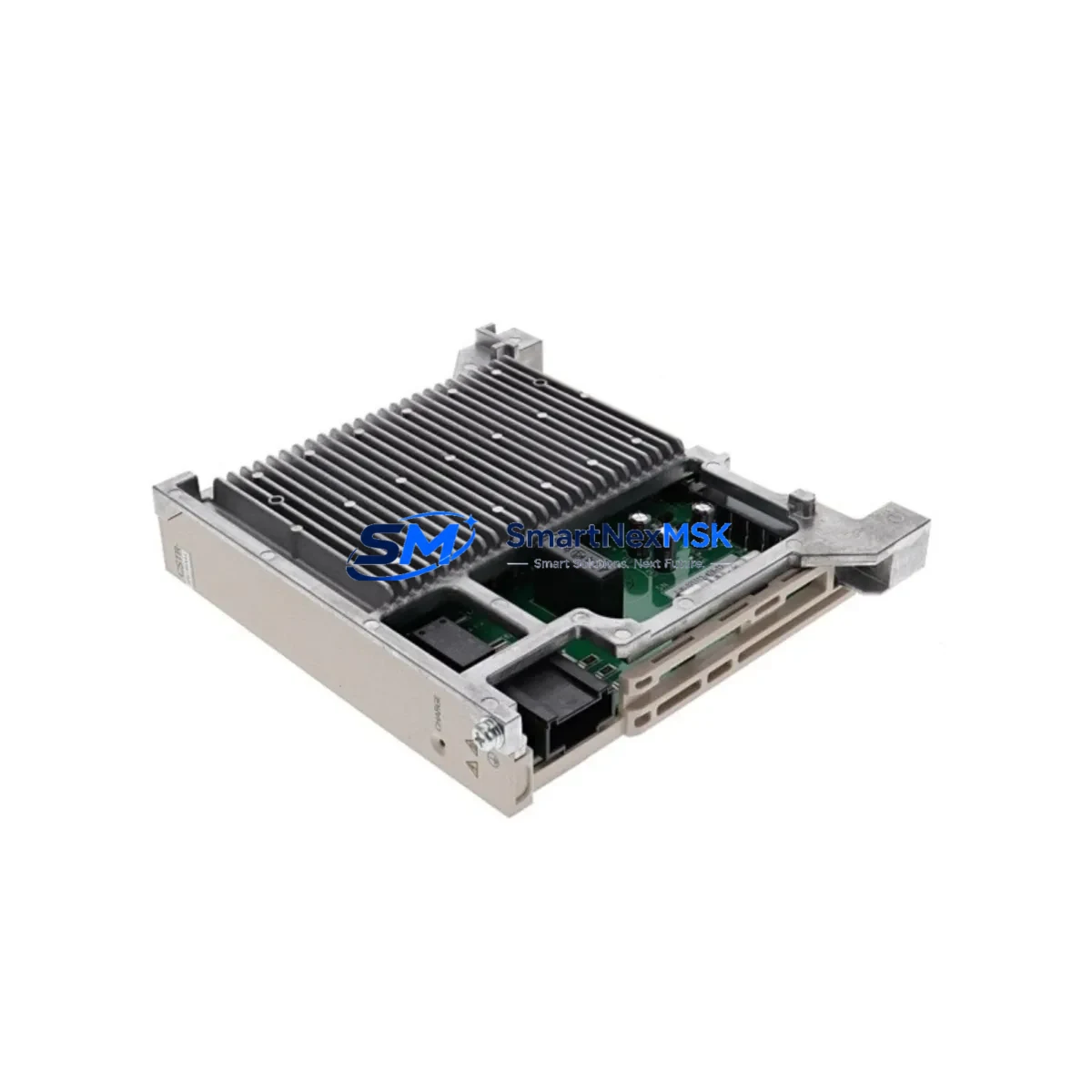
The YASKAWA DESIG 3PCB YWP-EF is an original current transformer PCB board engineered for YASKAWA YWP-series AC drive systems. In industrial environments where unplanned downtime translates directly into production loss, having a verified, tested spare of this board on hand is a fundamental element of any proactive maintenance strategy. This board serves as the current sensing backbone of the drive’s feedback loop — responsible for accurate phase-current measurement, overcurrent detection, and protection signal generation. When this component degrades or fails, the drive may trip on OC (overcurrent), display erratic torque response, or shut down entirely, halting the controlled process.
Sourced directly from YASKAWA’s original manufacturing supply chain, each DESIG 3PCB YWP-EF unit supplied by SMARTNEXMSK is inspected, function-tested prior to dispatch, and backed by a 12-month warranty. Long-term supply continuity is maintained for legacy YWP-series installations, supporting old-system life extension programs where full drive replacement is not yet economically justified.
Spare Maintenance Table
| Parameter | Specification / Detail |
|---|---|
| Part Number / SKU | DESIG 3PCB YWP-EF |
| Brand | YASKAWA |
| Series Compatibility | YASKAWA YWP-EF Series AC Drive Systems |
| Function | Current Transformer PCB Board — phase current sensing, OC protection signal |
| Board Type | Original OEM PCB Assembly |
| Origin | Japan (JP) |
| Application Environment | Industrial control cabinets, AC drive enclosures, motor control centers |
| Installation | Direct board-level replacement; match connector orientation and mounting points |
| Compatibility Verification | Confirm drive nameplate series and firmware revision before installation |
| Pre-Shipment Testing | Function-tested prior to dispatch |
| Warranty | 12 Months from date of shipment |
| Maintenance Recommendation | Replace as part of scheduled PCB inspection cycle; inspect every 3–5 years or after OC fault events |
| Supply Status | Long-term stock maintained for legacy YWP-EF installations |
Maintenance Planning for Continuous Operation
When a maintenance or procurement engineer schedules replacement of the DESIG 3PCB YWP-EF, the scope of inspection should extend beyond the PCB itself. The current transformer board operates within a tightly integrated electrical circuit, and adjacent components are subject to the same thermal and electrical stress cycles. A thorough site inspection during the same maintenance window significantly reduces the risk of a secondary failure shortly after the primary repair.
Begin with the drive’s main power supply board and DC bus capacitor bank — capacitor aging is a leading cause of voltage ripple that accelerates PCB component wear. Inspect the gate driver board and IGBT module for signs of thermal fatigue or carbon tracking, as overcurrent events that damage the YWP-EF PCB often originate from IGBT degradation. Check all control terminal wiring and I/O signal cables for insulation cracking, loose ferrules, or corrosion at the terminal block — the YASKAWA YWP-series terminal board should be cleaned and torque-verified at each planned maintenance interval.
The communication interface card (MECHATROLINK, DeviceNet, or PROFIBUS depending on system configuration) should be seated firmly and its connector inspected for oxidation. If the drive interfaces with a YASKAWA operator panel (digital operator / HMI), verify the keypad cable continuity and display function. Inspect input fuses and AC reactor on the supply side — a blown fuse or degraded reactor can cause asymmetric phase loading that stresses the current sensing circuit. The braking resistor and braking unit (if fitted) should be checked for resistance drift and thermal discoloration. Finally, review the cooling fan assembly and heatsink condition; restricted airflow is a primary driver of PCB thermal degradation in enclosed drive cabinets. Where signal isolators are used between the drive’s analog output and the PLC/DCS analog input card, verify isolation integrity and zero/span calibration.
Documenting all findings in the site maintenance log and updating the spare parts inventory record ensures that the next planned inspection cycle can be scheduled with full visibility of component age and replacement history.
Site Replacement Workflow
1. Isolation and lockout: De-energize the drive, apply LOTO (Lockout/Tagout), and wait for DC bus discharge (minimum 5 minutes; verify with a calibrated voltmeter before touching internal components).
2. Documentation: Photograph the existing board orientation, connector positions, and any visible fault indicators (burnt marks, swollen components) before removal. Record the drive’s parameter settings if accessible.
3. Board removal: Disconnect all connectors in sequence, noting cable labels. Remove mounting screws and extract the DESIG 3PCB YWP-EF board using an ESD-safe handling procedure.
4. Inspection of mating connectors: Clean connector pins on the drive chassis side with contact cleaner. Inspect for bent pins or heat damage before installing the replacement board.
5. Installation: Seat the new DESIG 3PCB YWP-EF board, secure mounting screws to the specified torque, and reconnect all connectors in reverse removal order. Verify no cables are pinched or strained.
6. Power-up and verification: Re-energize the drive and monitor for fault codes. Run the drive at low speed under no-load conditions and verify current feedback readings on the operator panel or via the connected HMI/SCADA. Confirm OC protection thresholds are within specification.
7. System handover: Update the maintenance record, affix a replacement date label to the board location, and replenish the spare parts stock to maintain buffer inventory for future events.
This workflow minimizes total downtime from fault detection to system restoration, typically enabling same-shift recovery when a verified spare is available on-site.
Spare Parts Support FAQ
Q1: Is the DESIG 3PCB YWP-EF compatible with all YWP-series drive ratings?
The DESIG 3PCB YWP-EF is designed for the YASKAWA YWP-EF series. Compatibility should be confirmed against the drive’s nameplate model number and internal revision label before ordering. Contact our technical team with your drive’s full model code for pre-order compatibility verification.
Q2: What does the 12-month warranty cover?
The 12-month warranty covers manufacturing defects and functional failure under normal operating conditions from the date of shipment. Each unit is function-tested prior to dispatch. Warranty claims are supported with replacement or refund; field installation damage or misapplication is excluded.
Q3: How quickly can the spare be shipped, and what is the recommended stock level?
Standard dispatch is within 1–3 business days of order confirmation. For critical production lines running YASKAWA YWP-EF drives, we recommend maintaining a minimum of one DESIG 3PCB YWP-EF board per drive cluster in the site spare parts store. For multi-drive installations, a 1:5 ratio (one spare per five drives) is a common industry practice for PCB-level components.
Q4: Can this board be used to replace an older or discontinued YWP-EF PCB revision?
In many cases, current-production OEM boards are backward-compatible with earlier drive revisions within the same series. However, revision-level compatibility must be verified against the drive’s internal documentation or YASKAWA service bulletin. Our team can assist with cross-reference verification prior to shipment.
© 2026 SMARTNEXMSK. All rights reserved.
Original Source: https://smartnexmsk.com
Contact: [email protected] | +86 18259474341