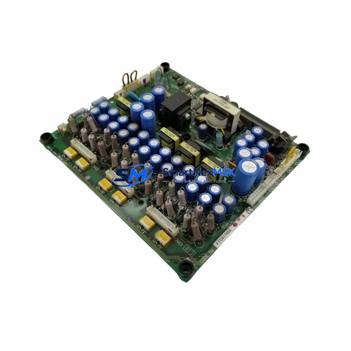
YASKAWA YPHT31295-1D Maintenance-Ready Spare for Sigma Automation
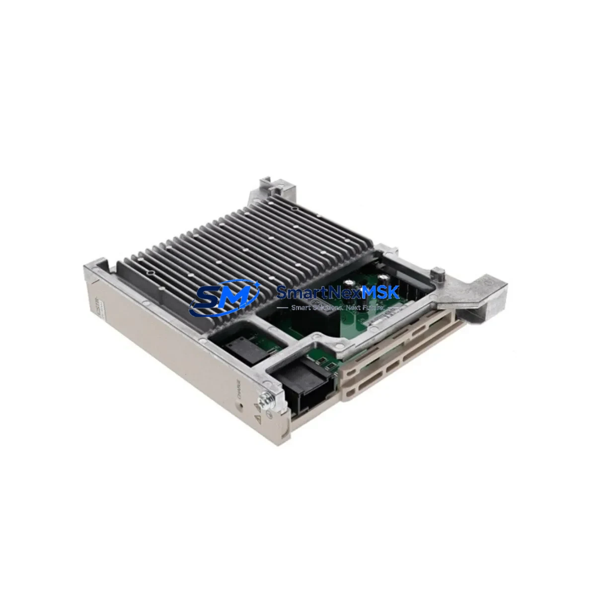
The YASKAWA YPHT31295-1D is an original panel power board designed for the Sigma-Series servo drive family — one of the most widely deployed servo amplifier platforms in precision manufacturing, packaging, semiconductor handling, and CNC automation. When this board fails, the entire servo axis goes offline, halting production and triggering unplanned downtime. Stocking a verified replacement is the most effective strategy for minimizing mean time to repair (MTTR) and protecting continuous operation in servo-dependent control systems.
This unit is sourced as an original YASKAWA spare, not a counterfeit or remanufactured substitute. Each board undergoes functional inspection and electrical verification prior to shipment. A 12-month warranty is included, covering defects in materials and workmanship under normal industrial operating conditions. Fast worldwide dispatch ensures your maintenance team receives the part when it is needed most — not weeks later.
Spare Maintenance Table
| Parameter | Specification / Detail |
|---|---|
| Part Number | YPHT31295-1D |
| Brand | YASKAWA |
| Series | Sigma-Series (Sigma-II / Sigma-III / Sigma-V compatible variants) |
| Component Type | Panel Power Board / Internal Power Supply Board |
| Application | Servo amplifier internal power regulation and gate drive supply |
| Input Voltage | Per host servo drive specification (typically 200–230 VAC or 380–480 VAC) |
| Compatibility | YASKAWA Sigma-Series servo drives; verify drive model before installation |
| Origin | Japan |
| Condition | Original, new or tested-serviceable |
| Pre-shipment Test | Functional electrical verification performed |
| Warranty | 12 Months — defects in materials and workmanship |
| Installation Environment | Industrial control cabinet; IP20 minimum enclosure recommended |
| Maintenance Interval | Inspect at scheduled PM; replace proactively at first sign of capacitor bulge, burn marks, or erratic drive faults |
| Lead Time | In-stock units ship within 1–3 business days |
Maintenance Planning for Continuous Operation
A servo drive power board failure rarely occurs in isolation. When the YPHT31295-1D is replaced during a corrective or planned maintenance event, experienced maintenance engineers use the opportunity to inspect and verify the condition of all interdependent components in the same servo axis and control cabinet. Overlooking adjacent components is a leading cause of repeat failures and secondary unplanned downtime.
During the same maintenance window, the following components should be inspected or replaced as part of a comprehensive servo axis restoration:
- YASKAWA Sigma-Series Servo Amplifier Main Board — the control logic board that interfaces with the power board; check for corrosion, cracked solder joints, and firmware version compatibility before reinstalling.
- SGDV / SGDH Series Gate Drive Board — the IGBT gate driver board works in close electrical proximity to the YPHT31295-1D; thermal stress on one board often affects the other.
- DC Bus Capacitor Bank — electrolytic capacitors in the servo drive DC bus degrade over time; bulging or leaking capacitors are a primary cause of power board stress and should be replaced simultaneously.
- Regenerative Resistor and Braking Unit — if the drive has been operating in high-cycle or high-inertia applications, the regenerative braking resistor should be checked for open-circuit or thermal damage.
- YASKAWA CN1 / CN2 Encoder Feedback Cable — damaged or intermittently shielded encoder cables cause erratic position feedback, which can generate fault codes that mimic power board failures; inspect and replace if shielding is compromised.
- I/O Terminal Block and Wiring Harness — loose or corroded terminals on the servo drive I/O connector (SEN, ALM, S-ON, P-CON signals) can cause nuisance faults; clean and re-torque all terminals during the maintenance window.
- 24 VDC Control Power Supply Module — the servo drive control circuit depends on a stable 24 VDC rail; verify output voltage and ripple with a multimeter before declaring the power board as the root cause.
- MCCB / Fuse Protection on the Servo Drive Input — check the molded case circuit breaker or fast-acting fuse on the servo drive input line; a power board failure caused by an upstream surge may have also weakened the protective device.
- YASKAWA JUSP-OP05A-1 or Compatible Digital Operator / HMI Panel — if the drive uses a local operator panel for parameter display and fault history, verify the panel communication is restored after board replacement and that fault logs are cleared.
- Communication Module (MECHATROLINK-II/III or EtherCAT Option Card) — if the Sigma-Series drive uses a fieldbus option card for motion network integration, confirm the card is reseated and the network address is correctly configured after the power board swap.
Procurement engineers sourcing the YPHT31295-1D for safety stock should consider maintaining a minimum of one unit per servo axis in critical production lines, with a secondary buffer for high-utilization machines. Pairing this board with a spare gate drive board and a set of DC bus capacitors creates a complete servo drive repair kit that enables field technicians to restore a failed drive without waiting for external repair services.
Site Replacement Workflow
Replacing the YPHT31295-1D in the field follows a structured procedure to ensure system compatibility and minimize the risk of secondary damage:
- Isolate and de-energize — disconnect main power and 24 VDC control power from the servo drive. Verify zero voltage with a calibrated meter before opening the drive enclosure. Allow the DC bus capacitors to discharge fully (minimum 5 minutes after power-off).
- Document the existing configuration — photograph the wiring harness routing, connector positions, and any parameter settings displayed on the operator panel before disassembly. This is critical for older Sigma-II and Sigma-III drives where parameter backup may not be automated.
- Remove the failed board — carefully disconnect all ribbon cables and board-to-board connectors. Note the orientation of each connector. Remove mounting screws and extract the YPHT31295-1D from the drive chassis.
- Inspect the drive chassis — before installing the replacement board, inspect the drive chassis for burn marks, contamination, or damaged connector pins that may have caused the original failure.
- Install the replacement YPHT31295-1D — seat the board firmly, reconnect all cables in the documented sequence, and secure mounting screws to the specified torque.
- Power-up and verify — restore 24 VDC control power first and confirm the operator panel initializes without fault codes. Then restore main power and perform a no-load servo enable test before reconnecting the mechanical load.
- Restore parameters and test — reload saved parameters if available, or re-enter manually from the documented settings. Run a full motion test cycle and verify encoder feedback, torque limits, and alarm thresholds are within specification.
This workflow is applicable to legacy Sigma-II and Sigma-III drives as well as current Sigma-V and Sigma-7 platforms where the YPHT31295-1D is a compatible internal component. The structured approach reduces average replacement time and eliminates the most common causes of repeat failures after board-level repair.
Spare Parts Support FAQ
Q1: Is the YPHT31295-1D compatible with all Sigma-Series servo drives?
The YPHT31295-1D is designed for specific models within the YASKAWA Sigma-Series family. Compatibility depends on the host drive model number, power rating, and hardware revision. Always cross-reference the drive nameplate model number with the board part number before ordering. Our technical team can assist with compatibility verification prior to purchase.
Q2: What testing is performed before shipment?
Each YPHT31295-1D unit undergoes functional electrical inspection before dispatch. This includes verification of output voltage rails, insulation resistance checks, and visual inspection for component damage. Units that do not pass inspection are not shipped. A 12-month warranty covers defects identified after installation under normal operating conditions.
Q3: How should the YPHT31295-1D be stored as a spare part?
Store in the original anti-static packaging in a dry, temperature-controlled environment (recommended: 0–40°C, relative humidity below 75% non-condensing). Avoid storing near strong magnetic fields or in environments with conductive dust. Inspect the board annually if held in long-term storage and replace the anti-static bag if it shows signs of degradation.
Q4: What is the recommended spare parts strategy for facilities running multiple Sigma-Series servo axes?
For facilities with five or more Sigma-Series servo axes, maintaining at least one YPHT31295-1D in on-site safety stock is strongly recommended. For critical production lines where servo downtime directly halts output, a two-unit buffer is advisable. Pair the power board spare with a gate drive board and a set of DC bus capacitors to enable complete drive restoration without external repair services. Review and replenish safety stock after each corrective maintenance event.
© 2026 SMARTNEXMSK. All rights reserved.
Original Source: https://smartnexmsk.com
Contact: [email protected] | +86 18259474341