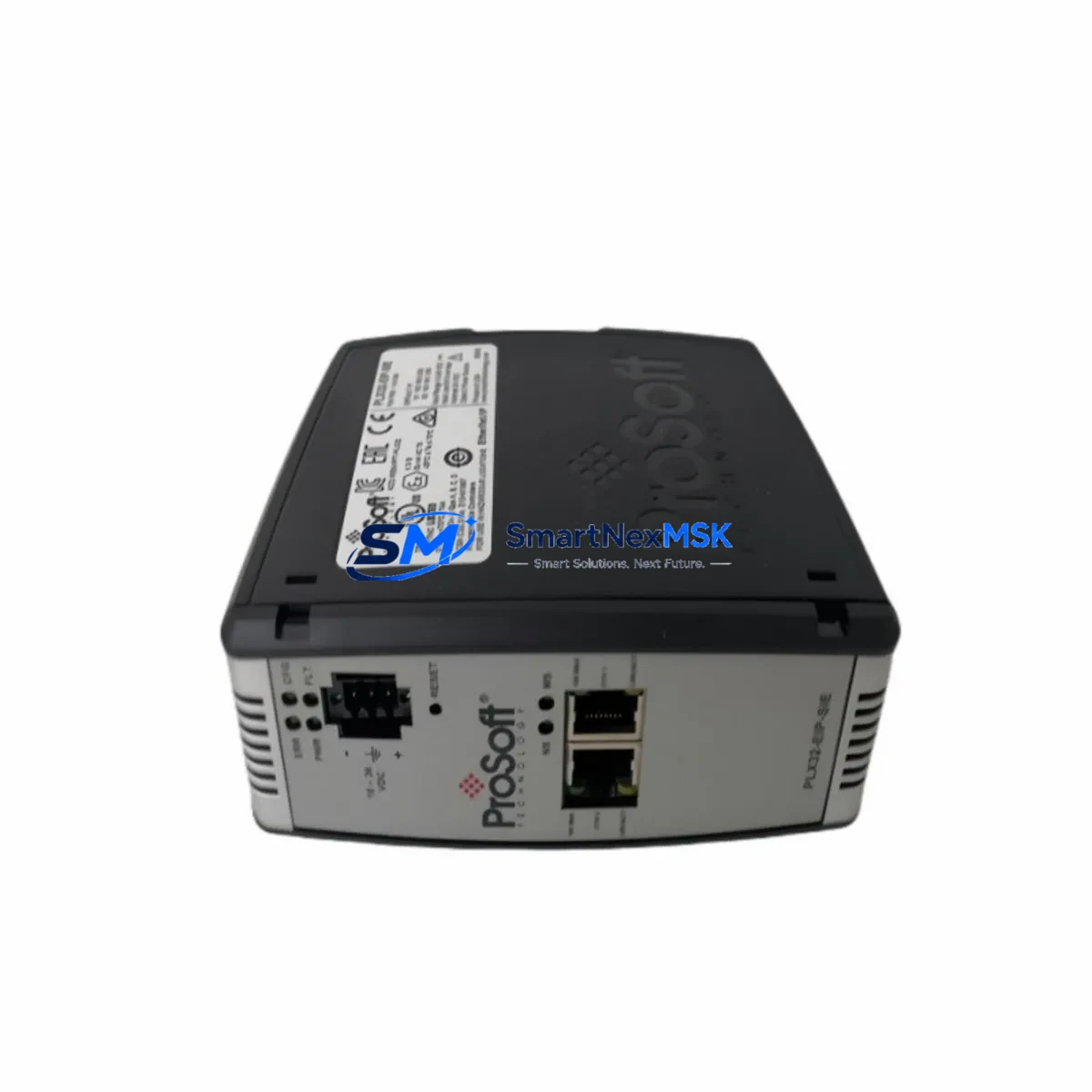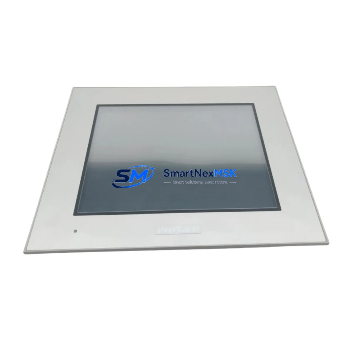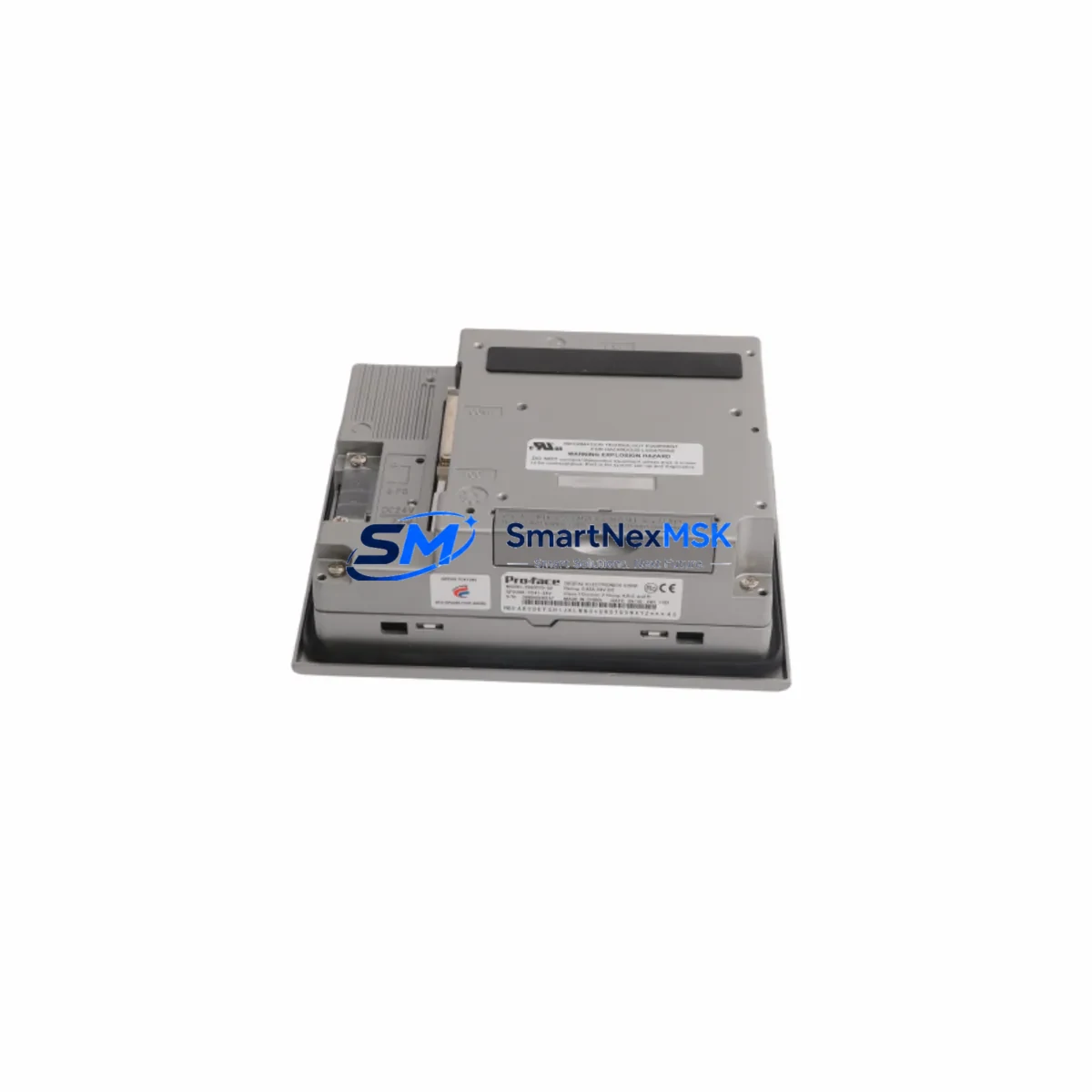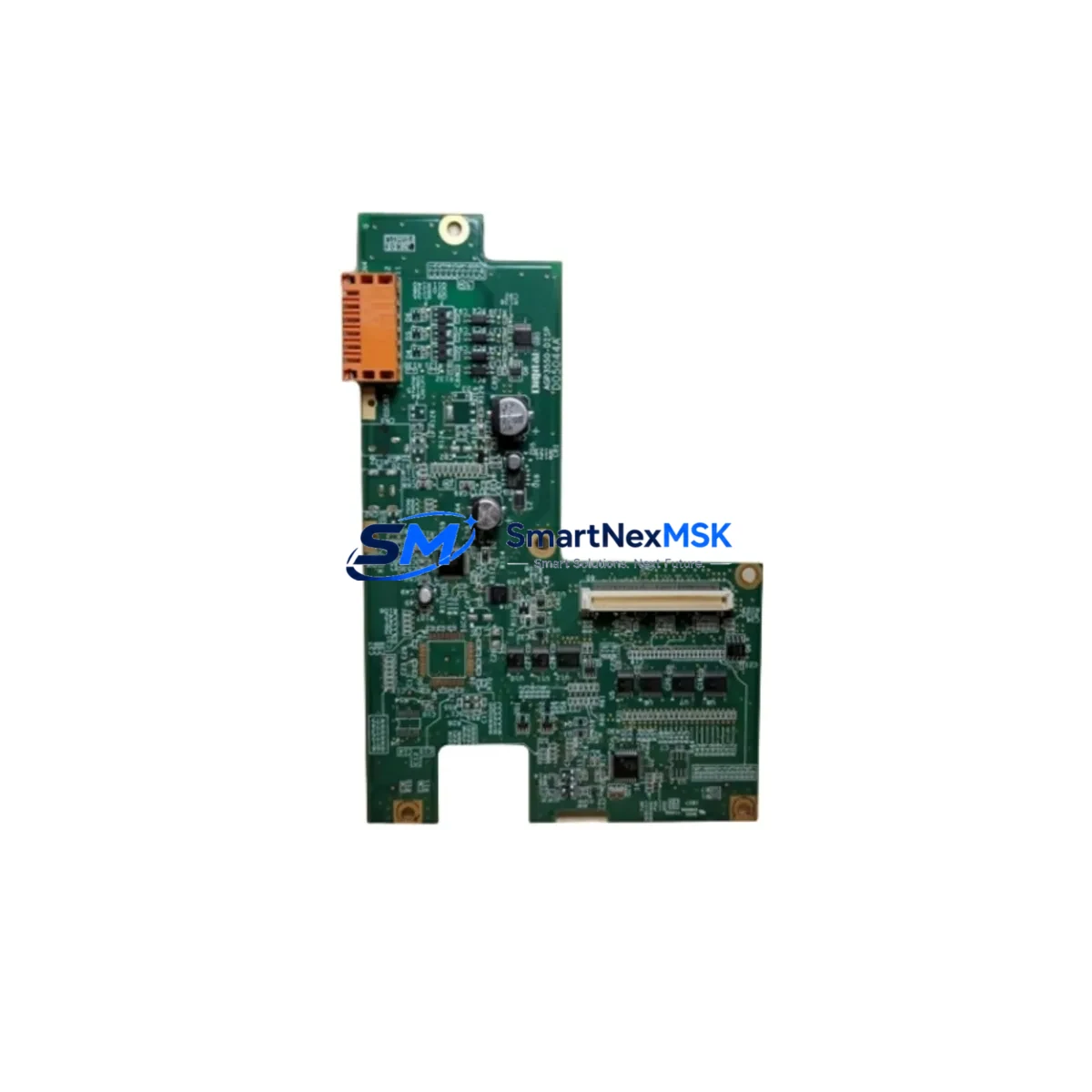
Proface AGP3550-DISP D05044A Retrofit-Ready HMI Display for AGP3550 Control Systems
The Proface AGP3550-DISP D05044A is a retrofit-ready HMI display driver board engineered as a direct replacement for the AGP3550 series operator panel. As legacy Proface AGP3550 units reach end-of-service life across manufacturing lines, food processing facilities, and discrete automation cells, sourcing a verified, compatible display assembly becomes critical to maintaining uptime. This module restores full panel functionality — including touch response, backlight operation, and serial communication — without requiring PLC program modification or HMI screen redesign.
Whether you are recovering from a sudden display failure, executing a planned control cabinet upgrade, or building a spare-parts inventory for a multi-site AGP3550 deployment, the AGP3550-DISP D05044A provides a proven, cost-effective path to system continuity. Each unit is pre-tested prior to shipment and backed by a 12-month warranty.
Upgrade Compatibility Table
| Parameter | AGP3550-DISP D05044A | Notes |
|---|---|---|
| Target Platform | Proface AGP3550 Series | Covers AGP3550-T1-D24, AGP3550-T1-AF, and related variants |
| Display Interface | Internal flat-flex connector (FFC) | Matches OEM connector pitch and locking tab orientation |
| Backlight Type | LED backlight assembly | Replaces CCFL-era units; no inverter board modification required |
| Touch Panel Compatibility | Resistive touch overlay retained | Existing touch panel and controller board remain in place |
| Communication Links | RS-232 / RS-422 / Ethernet (via host board) | No protocol reconfiguration needed at display-board level |
| Installation Requirement | ESD-safe disassembly; no soldering | Standard Proface service procedure applies |
| Retrofit Recommendation | Direct board swap | Retain original gasket and front bezel |
| Commissioning Focus | Touch calibration, brightness check | Run Proface GP-Pro EX diagnostics post-installation |
| Warranty | 12 Months | Covers manufacturing defects; includes pre-shipment functional test |
Retrofit Planning for Existing Automation Systems
A successful AGP3550 display retrofit extends well beyond swapping the display board. In practice, the replacement process intersects with several adjacent components and subsystems that must be assessed before and during the upgrade.
Begin by auditing the AGP3550 power supply rail: the panel requires a stable 24 VDC input, and aging cabinet power supplies — particularly units shared with Proface GP2000 or GP3000 series panels on the same rail — may exhibit voltage sag under load. Verify supply capacity before energizing the replacement display board.
Next, inspect the terminal wiring harness connecting the AGP3550 to the host PLC. In many legacy installations, the panel communicates with a Mitsubishi Q-series CPU module or a Siemens S7-300 CPU via RS-422 or Ethernet/IP. Confirm that the communication cable — typically a Proface CA3-CBLTB00-01 or equivalent — is undamaged and that the host PLC’s communication port settings (baud rate, parity, station number) remain unchanged after the display swap.
For systems where the AGP3550 is mounted in a multi-panel control cabinet alongside Proface AGP3600 or AGP3500 units sharing a common backplane or DIN rail, verify that the cabinet’s internal grounding bus is intact. Display board replacements in shared-ground enclosures occasionally introduce ground loop noise if the replacement unit’s chassis bonding differs from the original.
If the AGP3550 is connected to a remote I/O rack — such as a Proface FP-X0 expansion unit or a third-party DeviceNet I/O block — confirm that the I/O polling cycle resumes correctly after the panel restarts. Some configurations require a manual re-initialization of the I/O map within GP-Pro EX if the panel’s internal clock resets during the board swap.
For installations where the AGP3550 serves as the primary HMI for a Yokogawa FA-M3 controller or an Omron CJ2M CPU, review the screen project file in GP-Pro EX before disassembly. Export and archive the current project to a PC. After reinstalling the display board and powering up, re-download the project to confirm that all tag addresses, alarm setpoints, and trend display configurations are intact.
In retrofit scenarios involving communication protocol migration — for example, transitioning from a legacy RS-232 link to Ethernet/IP — the display board replacement is an ideal intervention point. The AGP3550’s host board supports Ethernet connectivity natively; the display swap does not affect this capability, but the migration should be planned and tested in a staging environment before live cutover.
Finally, if the control cabinet also houses a Proface GP-4501T or a newer GP4000 series panel as a secondary display, ensure that the HMI project files for both panels are version-controlled and backed up. Mixed-generation panel environments are common in phased upgrade projects, and maintaining project file parity across units prevents screen inconsistencies during the transition period.
Downtime Control During System Migration
Minimizing production downtime during an AGP3550 display replacement requires preparation, not improvisation. The following approach has been validated across multiple industrial retrofit projects:
Pre-shutdown preparation: Before taking the panel offline, capture screenshots of all active HMI screens, record current alarm states, and export the GP-Pro EX project file. If the AGP3550 is controlling a critical process loop — such as a temperature PID managed by a connected Proface LT4000M or a standalone PLC — confirm that the PLC will maintain its last output state (hold mode) during the HMI communication interruption. Most Mitsubishi FX5U and Q-series CPUs support this natively; verify the setting in GX Works before proceeding.
During replacement: Work in an ESD-safe environment. Disconnect the 24 VDC supply before opening the panel enclosure. The display board is secured by four Phillips screws and the FFC connector; the swap typically takes 15–25 minutes for a technician familiar with the AGP3550 chassis. Do not force the FFC latch — it is a zero-insertion-force (ZIF) type that lifts vertically.
Post-installation commissioning: Power up the panel and allow the Proface OS to complete its boot sequence (approximately 45–60 seconds). Run the built-in touch calibration routine from the panel’s offline menu. Verify communication link status in the GP-Pro EX transfer tool — a green link indicator confirms that the host PLC connection has been re-established. Confirm that all HMI screens display correctly and that alarm acknowledgment functions are operational before returning the line to production.
With proper preparation, total downtime for an AGP3550-DISP D05044A swap is typically under 60 minutes, including commissioning and sign-off.
Retrofit Support FAQ
Q1: Is the AGP3550-DISP D05044A a direct drop-in replacement for the original Proface display board?
Yes. The D05044A is designed as a form-fit-function replacement for the AGP3550 series display assembly. The FFC connector, mounting hole pattern, and board dimensions match the OEM specification. No mechanical modification to the panel chassis is required.
Q2: Will I need to reconfigure my PLC communication settings after the display swap?
No. The display board replacement does not affect the AGP3550’s host board, communication ports, or stored project file. Your RS-232, RS-422, or Ethernet link settings remain intact. However, we recommend verifying the communication link status in GP-Pro EX after power-up as a standard commissioning step.
Q3: How is the unit tested before shipment?
Each AGP3550-DISP D05044A undergoes a functional pre-shipment test covering display initialization, backlight operation, and FFC connector integrity. A test report is available upon request. The unit is shipped in anti-static packaging with corner protection to prevent transit damage.
Q4: What does the 12-month warranty cover?
The warranty covers manufacturing defects and component failures under normal operating conditions for 12 months from the date of shipment. It does not cover damage resulting from incorrect installation, overvoltage, or physical impact. Our technical team provides post-sale support for installation questions and compatibility verification at no additional charge.
© 2026 SMARTNEXMSK. All rights reserved.
Original Source: https://smartnexmsk.com
Contact: [email protected] | +86 18259474341