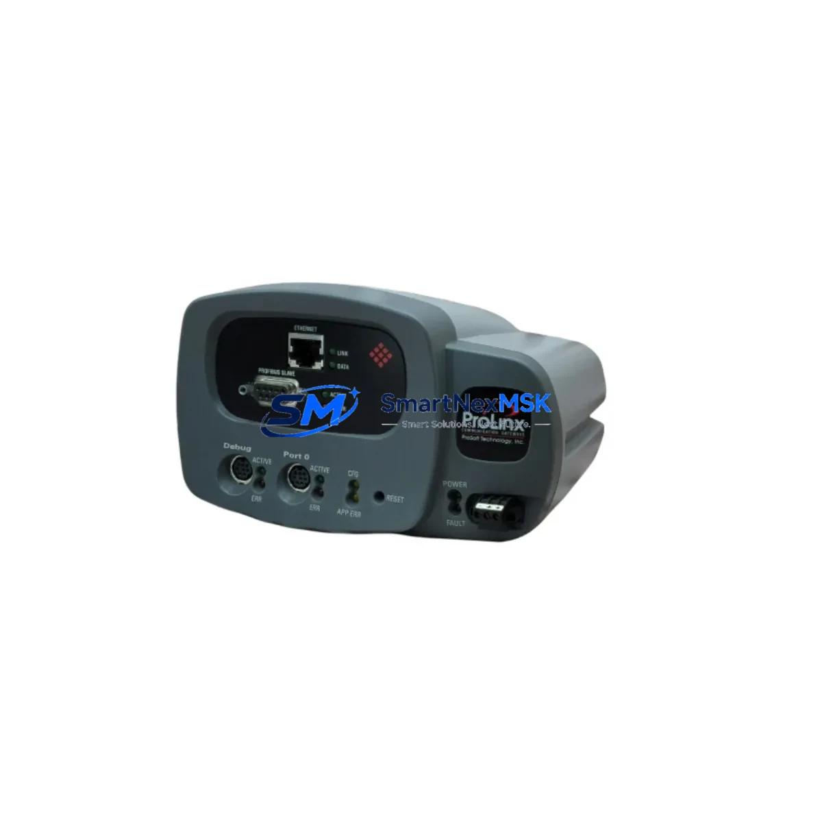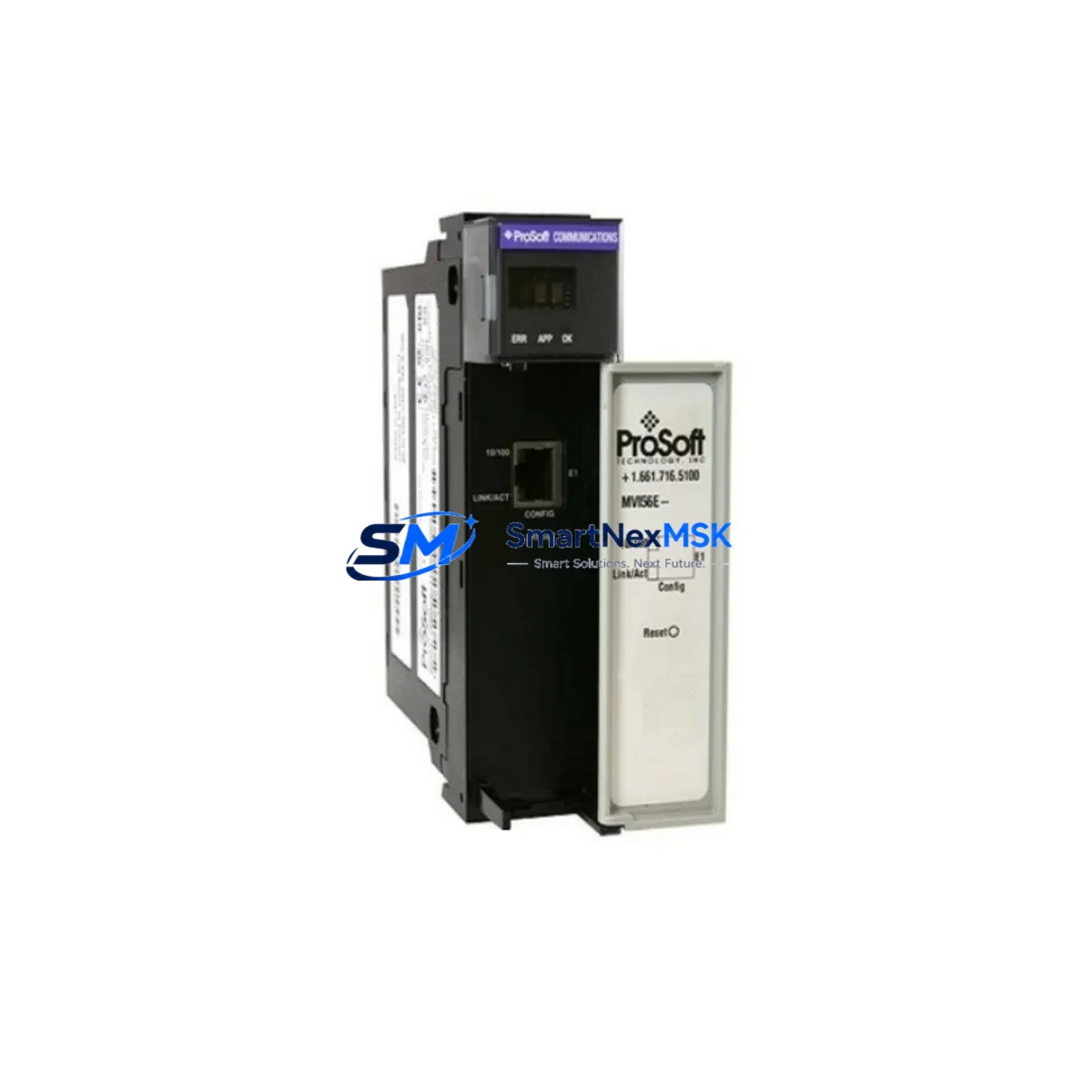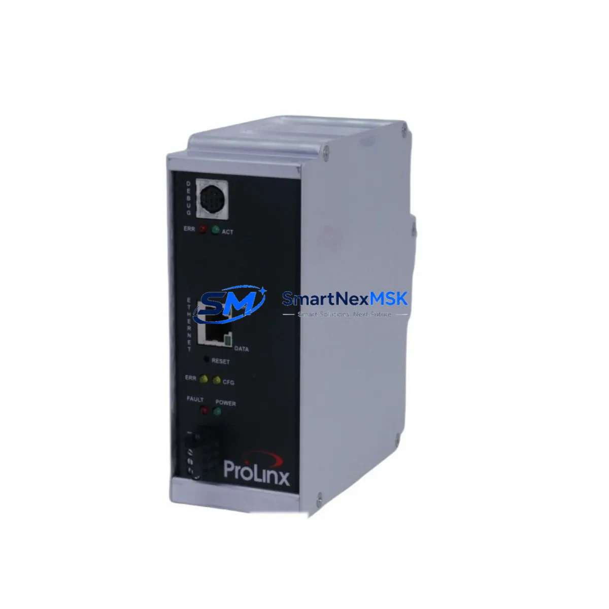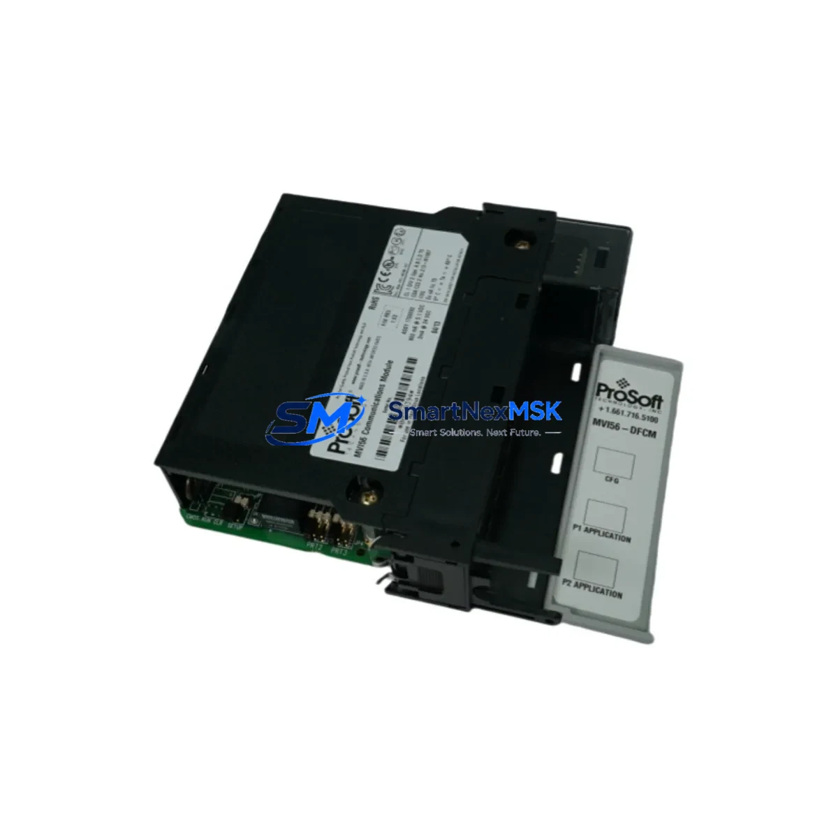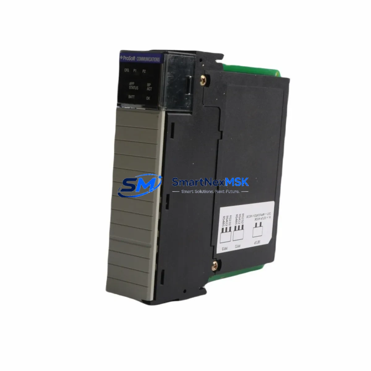
ProSoft MVI56-MDA4 Retrofit-Ready Gateway for ControlLogix Control Systems
The ProSoft MVI56-MDA4 is a high-performance communication gateway module engineered for seamless integration into Allen-Bradley ControlLogix backplane architectures. Designed as a retrofit-ready replacement for legacy CM4 gas analyzer interface modules and aging Modbus/DF1 serial communication cards, the MVI56-MDA4 delivers a smooth migration path for facilities operating older 1756-series control cabinets that require protocol modernization without full system replacement.
Whether your plant is retiring a discontinued serial communication card, upgrading a legacy DCS front-end, or expanding I/O capacity across a multi-rack ControlLogix chassis, the MVI56-MDA4 provides the compatibility, configurability, and field-proven reliability that industrial automation engineers demand. SMARTNEXMSK maintains verified stock of this module with full pre-shipment functional testing and a 12-month warranty on every unit.
Upgrade Compatibility Table
| Parameter | Details |
|---|---|
| Compatible Chassis | Allen-Bradley 1756-A4, 1756-A7, 1756-A10, 1756-A13, 1756-A17 ControlLogix backplanes |
| Replaces / Upgrades | Legacy CM4 gas analyzer interface cards, discontinued Modbus RTU serial modules, older DF1 communication adapters |
| Communication Protocols | Modbus RTU/ASCII (Master & Slave), DF1 Full/Half Duplex, User-Defined Serial |
| Serial Ports | 4 × RS-232/RS-422/RS-485 configurable ports |
| Installation Requirement | Standard 1756 single-slot; no special mounting hardware required |
| Backplane Interface | ControlLogix 1756 backplane; compatible with Logix5550, Logix5560, Logix5570, Logix5580 controllers |
| Configuration Tool | ProSoft Configuration Builder (PCB); RSLogix 5000 / Studio 5000 Add-On Profile |
| Commissioning Notes | Module address assignment via RSLogix 5000 I/O tree; verify slot number matches ladder logic configuration |
| Warranty | 12 months from date of shipment — covers manufacturing defects and functional failure under normal operating conditions |
Retrofit Planning for Existing Automation Systems
Successful integration of the MVI56-MDA4 into an existing control system begins well before the module arrives on site. Engineers should start by auditing the current 1756-series chassis to confirm available slot count and backplane power budget. The 1756-PA72 or 1756-PB72 power supply units commonly found in legacy ControlLogix cabinets must be verified to supply sufficient current for the additional communication module — the MVI56-MDA4 draws approximately 800 mA at 5 VDC from the backplane.
Terminal wiring is the next critical checkpoint. The four serial ports on the MVI56-MDA4 use RJ45 connectors with a ProSoft-specific pinout; adapters or custom cables may be required when replacing older DB9 or DB25 serial interfaces from the retired module. Confirm RS-232 vs. RS-485 wiring topology for each connected field device — gas analyzers, flow computers, and remote I/O nodes each have distinct cabling requirements.
For facilities running a 1756-ENBT or 1756-EN2T EtherNet/IP bridge alongside the serial gateway, ensure the Ethernet module firmware is current to avoid backplane communication conflicts. If the control cabinet also houses a 1756-DNB DeviceNet bridge or a 1756-RIO Remote I/O adapter, document their slot assignments before inserting the MVI56-MDA4 to prevent address collisions in the I/O configuration tree.
Program compatibility is equally important. Export and archive the existing RSLogix 5000 project before any hardware changes. The MVI56-MDA4 uses a structured Add-On Instruction (AOI) and a dedicated controller tag structure; these must be imported into the project and mapped to the correct module slot. If the legacy system used a 1747-KE or 1747-KFC15 serial interface on an older SLC 500 platform being migrated to ControlLogix, a full program conversion using the RSLogix 5000 migration utility is recommended prior to commissioning.
HMI screen updates are often overlooked during module swaps. If the facility uses a PanelView Plus 6 or PanelView 800 terminal communicating via DF1 to the legacy serial card, the communication path in FactoryTalk View ME must be reconfigured to reflect the new MVI56-MDA4 tag addresses. Verify all alarm setpoints, analog scaling factors, and trend historian tags remain intact after the migration.
Finally, for systems using a 1756-L71 or 1756-L83E controller with a 1585J-M8CBJM-2 Ethernet patch cable connecting to a managed switch, confirm that the network topology supports the additional serial-to-Ethernet traffic generated by the MVI56-MDA4’s pass-through messaging. A pre-commissioning loop check using ProSoft Configuration Builder’s diagnostic port monitor will confirm data flow on all four serial channels before the system is returned to production.
Downtime Control During System Migration
Minimizing unplanned downtime is the primary concern for any control system retrofit. When replacing a legacy serial communication module with the MVI56-MDA4, the recommended approach is a staged hot-swap procedure performed during a scheduled maintenance window. Begin by placing the ControlLogix controller in Program mode — do not power down the chassis unless the existing module is non-hot-swappable. Remove the legacy card, insert the MVI56-MDA4 into the same slot, and allow the backplane to recognize the new module before transitioning the controller back to Run mode.
To protect original program logic, always work from a verified backup of the RSLogix 5000 project stored on a separate engineering workstation. Use the controller’s partial import feature to add the MVI56-MDA4 AOI and tag structure without overwriting existing rungs. If the system uses produced/consumed tags shared across multiple controllers on the same ControlNet or EtherNet/IP network, verify that the tag producer controller is not the one being modified to avoid network-wide disruption.
For critical continuous-process applications — such as gas measurement, flow totalization, or environmental monitoring — consider deploying a temporary 1756-DHRIO or a portable serial data logger in parallel with the legacy module during the transition period. This allows field data to continue flowing to the historian or SCADA system while the new module is being configured and tested. Once the MVI56-MDA4 passes all loop checks and data integrity verifications, the parallel path can be removed and the system returned to normal operation with zero data loss.
Retrofit Support FAQ
Q1: Is the MVI56-MDA4 a direct drop-in replacement for the CM4 gas analyzer interface module?
The MVI56-MDA4 occupies the same single 1756 backplane slot and supports the same Modbus RTU and DF1 serial protocols used by the CM4 interface. However, the tag structure and AOI differ from the original CM4 driver, so RSLogix 5000 program modifications are required. SMARTNEXMSK provides a retrofit checklist to guide engineers through the tag remapping process.
Q2: What wiring changes are needed when replacing a DB9 serial card with the MVI56-MDA4?
The MVI56-MDA4 uses RJ45 serial port connectors. A DB9-to-RJ45 adapter cable with ProSoft’s pinout is required for each serial port connected to legacy DB9 field devices. ProSoft’s wiring diagram (available in the MVI56-MDA4 User Manual) specifies pin assignments for RS-232, RS-422, and RS-485 configurations. Verify termination resistor requirements for RS-485 multi-drop networks before commissioning.
Q3: Can the MVI56-MDA4 be commissioned without taking the entire ControlLogix chassis offline?
Yes. The 1756 ControlLogix platform supports hot insertion and removal of I/O and communication modules while the chassis remains powered. Place the controller in Program mode, insert the MVI56-MDA4, configure the module in RSLogix 5000, and return the controller to Run mode. Full chassis power-down is only required if the chassis power supply or backplane itself is being serviced.
Q4: What does the 12-month warranty cover, and how is it claimed?
Every MVI56-MDA4 unit shipped by SMARTNEXMSK carries a 12-month warranty covering manufacturing defects and functional failure under normal operating conditions. Pre-shipment functional testing is performed on all units. To initiate a warranty claim, contact [email protected] with the order number, module serial number, and a description of the fault. Replacement units are dispatched within 3 business days of claim verification.
© 2026 SMARTNEXMSK. All rights reserved.
Original Source: https://smartnexmsk.com
Contact: [email protected] | +86 18259474341