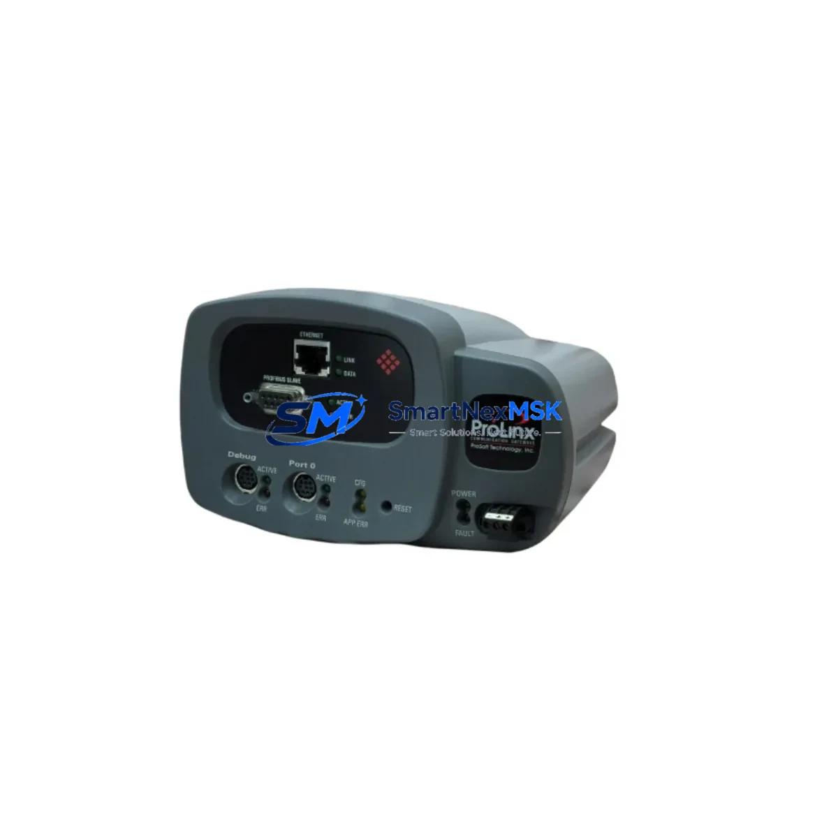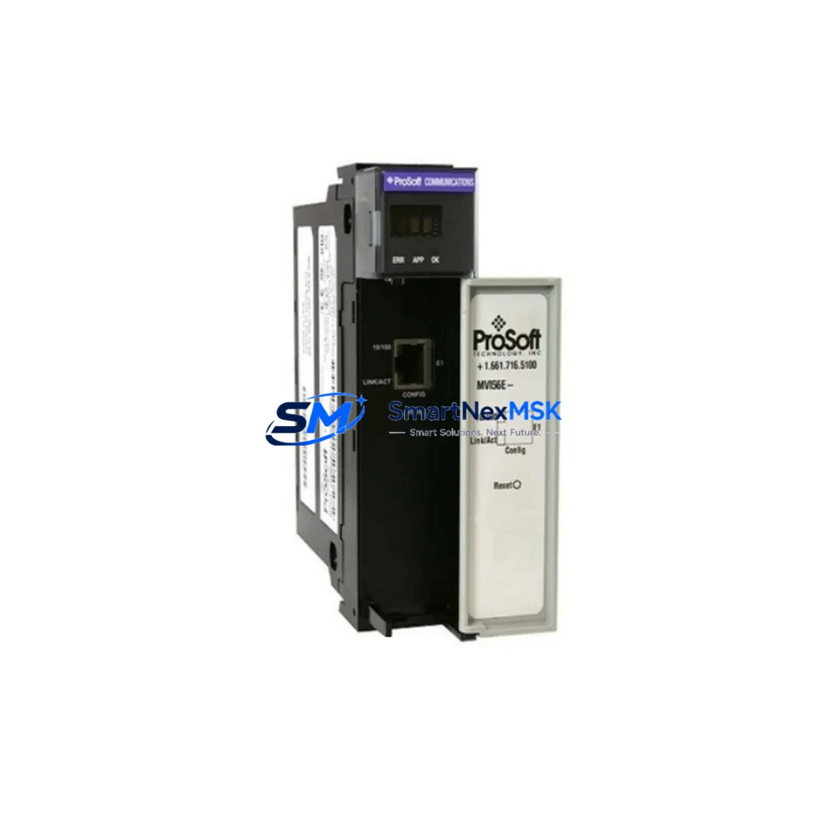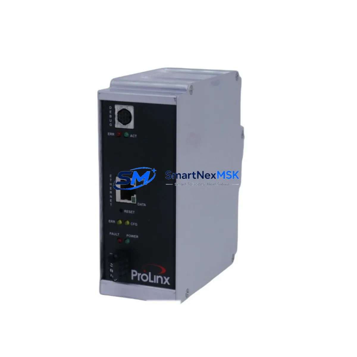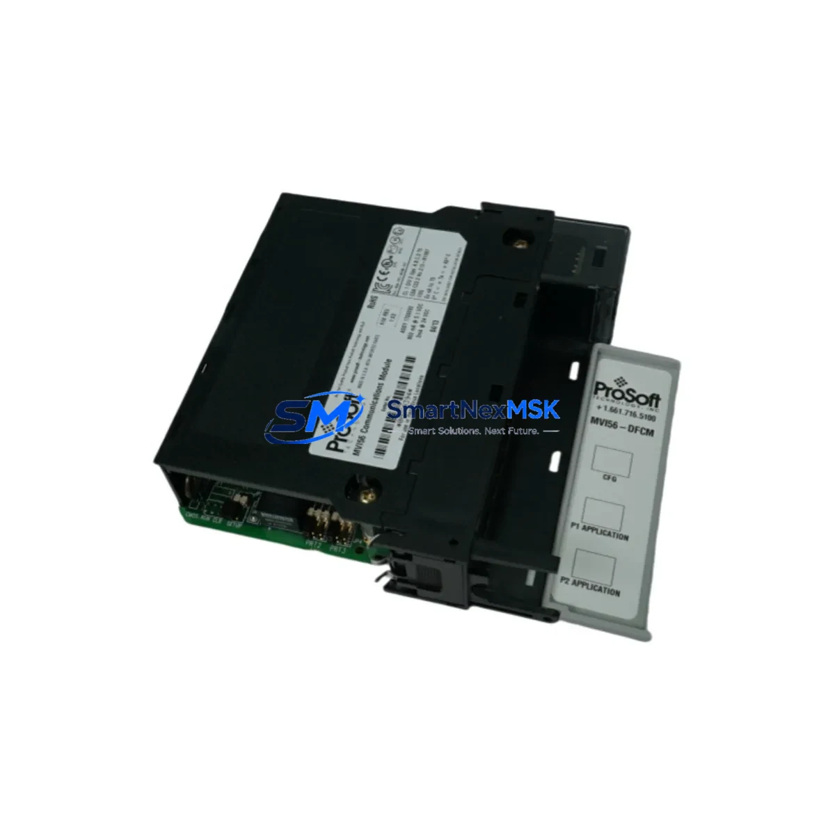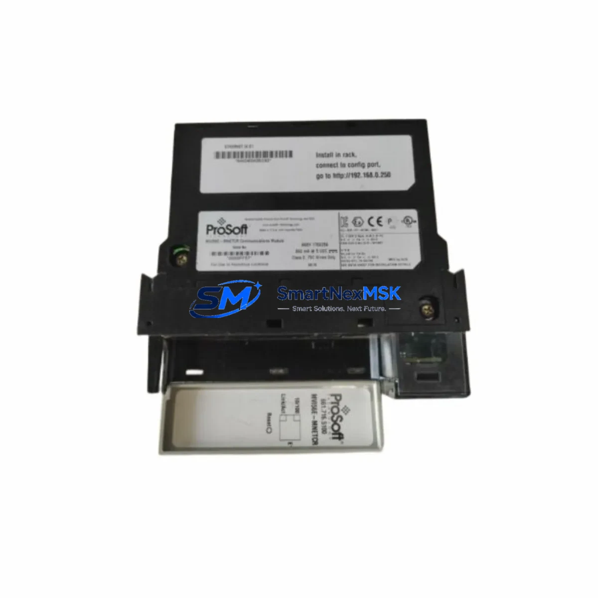
ProSoft MVI56E-MNETCR Retrofit-Ready Modbus TCP/IP Module for ControlLogix Control Systems
The ProSoft MVI56E-MNETCR is a high-performance Modbus TCP/IP Client/Server communication module engineered for Allen-Bradley ControlLogix backplane integration. Designed with legacy system modernization in mind, this module serves as a direct retrofit replacement for discontinued or end-of-life Modbus communication solutions across a wide range of industrial control platforms. Whether you are upgrading an aging DCS network, migrating from serial Modbus RTU to Ethernet-based Modbus TCP/IP, or restoring communication capability in a production-critical control cabinet, the MVI56E-MNETCR delivers the compatibility, reliability, and field-proven performance that industrial automation engineers demand.
The MVI56E-MNETCR supports up to 100 Modbus TCP/IP Client connections and 100 Server connections simultaneously, enabling seamless integration with third-party PLCs, SCADA systems, remote I/O panels, variable frequency drives, and intelligent field devices. Its onboard web server and ProSoft Configuration Builder (PCB) software simplify commissioning and reduce downtime during system migration. The module installs directly into any 1756 ControlLogix chassis slot and communicates with the Logix5000 controller via the ControlLogix backplane, eliminating the need for external gateways or protocol converters in most retrofit scenarios.
Upgrade Compatibility Table
| Parameter | Details |
|---|---|
| Compatible Chassis | Allen-Bradley 1756 ControlLogix (all generations) |
| Slot Requirement | 1 × ControlLogix I/O slot (any position) |
| Communication Protocol | Modbus TCP/IP Client & Server (RFC 1006 compliant) |
| Ethernet Interface | 10/100 Mbps RJ-45, auto-negotiation |
| Max Client Connections | 100 simultaneous Modbus TCP/IP Client sessions |
| Max Server Connections | 100 simultaneous Modbus TCP/IP Server sessions |
| Backplane Interface | ControlLogix 1756 backplane (standard) |
| Power Consumption | 800 mA @ 5 VDC (verify chassis power budget before installation) |
| Replacement for | MVI56-MNETC, MVI56-MNETR, legacy serial Modbus gateways |
| Programming Software | ProSoft Configuration Builder (PCB), RSLogix 5000 / Studio 5000 |
| Commissioning Tool | Onboard web server (browser-based diagnostics) |
| Warranty | 12 Months — covers hardware defects and factory configuration faults |
Retrofit Planning for Existing Automation Systems
Successful integration of the MVI56E-MNETCR into an existing control system requires careful pre-installation planning. Begin by auditing the current 1756 ControlLogix chassis power supply — typically a 1756-PA72 or 1756-PB72 — to confirm that sufficient 5 VDC backplane current is available after accounting for all installed modules. The MVI56E-MNETCR draws 800 mA at 5 VDC, and chassis power budgets must be recalculated whenever a new module is added, particularly in densely populated racks running 1756-IB16, 1756-OB16E, or 1756-IF8 analog input modules alongside the communication card.
Terminal wiring and Ethernet cabling should be verified against the existing network topology. In many retrofit projects, the MVI56E-MNETCR replaces a legacy MVI56-MNETC or an older serial Modbus RTU gateway connected through a 1756-DHRIO or 1756-CNB bridge module. When decommissioning the old communication path, document all existing Modbus register maps, device addresses, and polling intervals before removing the legacy hardware. The MVI56E-MNETCR’s configuration file — created in ProSoft Configuration Builder — must mirror these parameters exactly to avoid disrupting field device communication after cutover.
For systems that include a 1756-EN2T or 1756-EN3TR EtherNet/IP communication module sharing the same chassis, verify that IP address assignments and subnet configurations do not conflict with the MVI56E-MNETCR’s dedicated Ethernet port. In multi-rack installations connected via a 1756-RM2 redundancy module or a 1756-SYNCH synchronization cable, the module address and slot assignment must be consistent across both primary and secondary chassis to maintain redundancy integrity.
HMI screens built on FactoryTalk View SE or PanelView Plus terminals referencing Modbus data tags will require tag remapping if the underlying controller program structure changes during the upgrade. Coordinate with the HMI programmer to update any screen objects, alarm triggers, or trend pens that reference communication module data arrays before going live. Similarly, if the plant uses a SCADA platform polling the ControlLogix controller via OPC-DA or OPC-UA, confirm that the new Modbus data table addresses are reflected in the OPC server tag configuration.
Downtime Control During System Migration
Minimizing production downtime during a Modbus communication module replacement requires a structured cutover plan. Where possible, pre-configure the MVI56E-MNETCR offline using ProSoft Configuration Builder and validate the configuration file against a test bench or simulator before the scheduled maintenance window. Export and archive the existing controller program from Studio 5000 Logix Designer, including all Add-On Instructions (AOIs) and User-Defined Data Types (UDTs) associated with the legacy communication module, so that a rollback path is available if the cutover encounters unexpected issues.
During the physical swap, power down the chassis in a controlled sequence — disable field outputs first, then place the controller in Program mode, then remove chassis power. Install the MVI56E-MNETCR in the designated slot, restore power, and download the updated controller program. Use the module’s onboard web server to verify that Modbus TCP/IP connections are establishing correctly before returning the controller to Run mode. Monitor the first 15–30 minutes of live operation closely, paying particular attention to communication fault bits, data table integrity, and any watchdog timer alarms on connected field devices. A staged cutover approach — migrating one Modbus device group at a time rather than all connections simultaneously — further reduces risk and allows faster fault isolation if a device fails to respond after the upgrade.
Retrofit Support FAQ
Q: Is the MVI56E-MNETCR a direct drop-in replacement for the MVI56-MNETC?
A: Yes. The MVI56E-MNETCR occupies the same 1756 chassis slot and uses the same backplane interface as the MVI56-MNETC. The configuration file format has been updated for ProSoft Configuration Builder, so the legacy configuration must be re-entered or migrated using PCB’s import utility. Verify power budget and slot assignment before installation.
Q: Can the MVI56E-MNETCR operate as both a Modbus TCP/IP Client and Server simultaneously?
A: Yes. The module supports concurrent Client and Server operation, allowing it to poll remote Modbus devices while also responding to SCADA or HMI systems acting as Modbus Masters. Both roles are configured independently within the ProSoft Configuration Builder project file.
Q: What commissioning steps are required after installation?
A: After physical installation, assign the module’s Ethernet IP address via the onboard web server or PCB, download the configuration file, and verify backplane communication with the ControlLogix controller. Confirm Modbus TCP/IP connections are active using the module’s diagnostic web pages, then validate data table values against known field device registers before returning the system to automatic operation.
Q: What does the 12-month warranty cover?
A: The 12-month warranty covers hardware manufacturing defects and factory configuration faults from the date of shipment. Each unit undergoes functional testing prior to dispatch. Warranty claims are processed via our sales team with RMA authorization. Physical damage caused by incorrect installation, overvoltage, or environmental exposure is excluded from warranty coverage.
© 2026 SMARTNEXMSK. All rights reserved.
Original Source: https://smartnexmsk.com
Contact: [email protected] | +86 18259474341