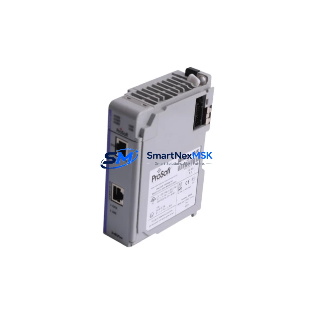
ProSoft MVI69-104S Retrofit-Ready IEC 104 for CompactLogix: Seamless Legacy System Upgrade
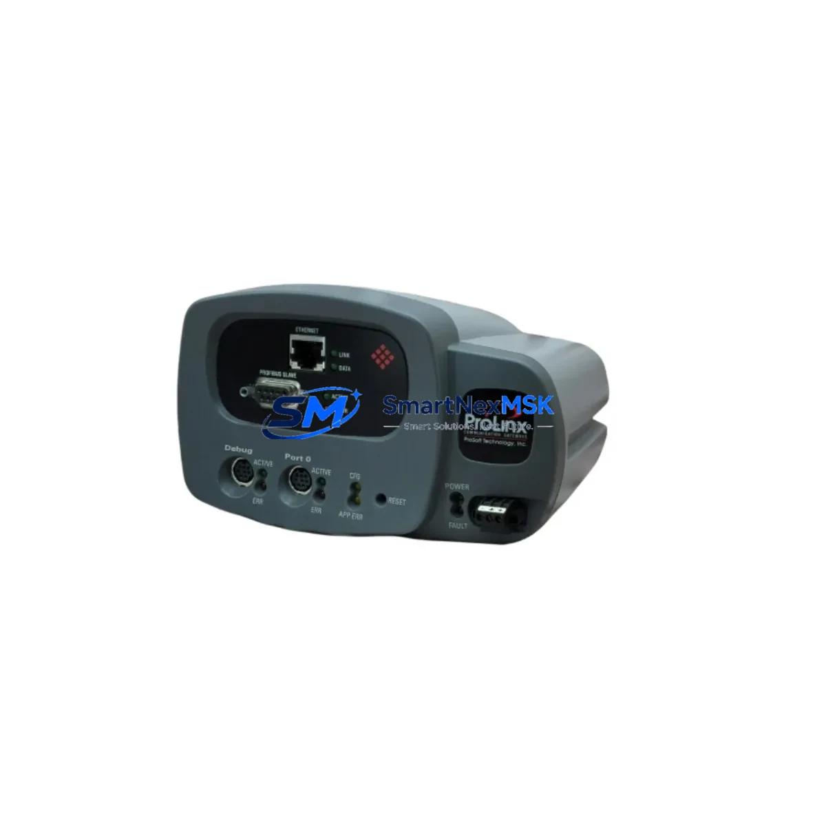
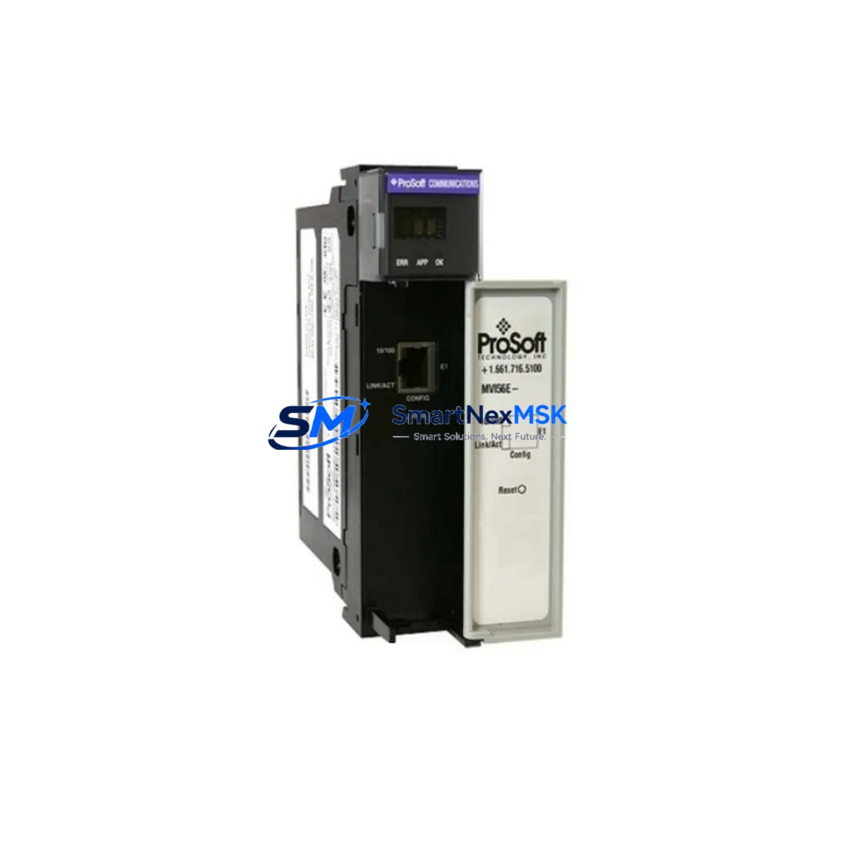
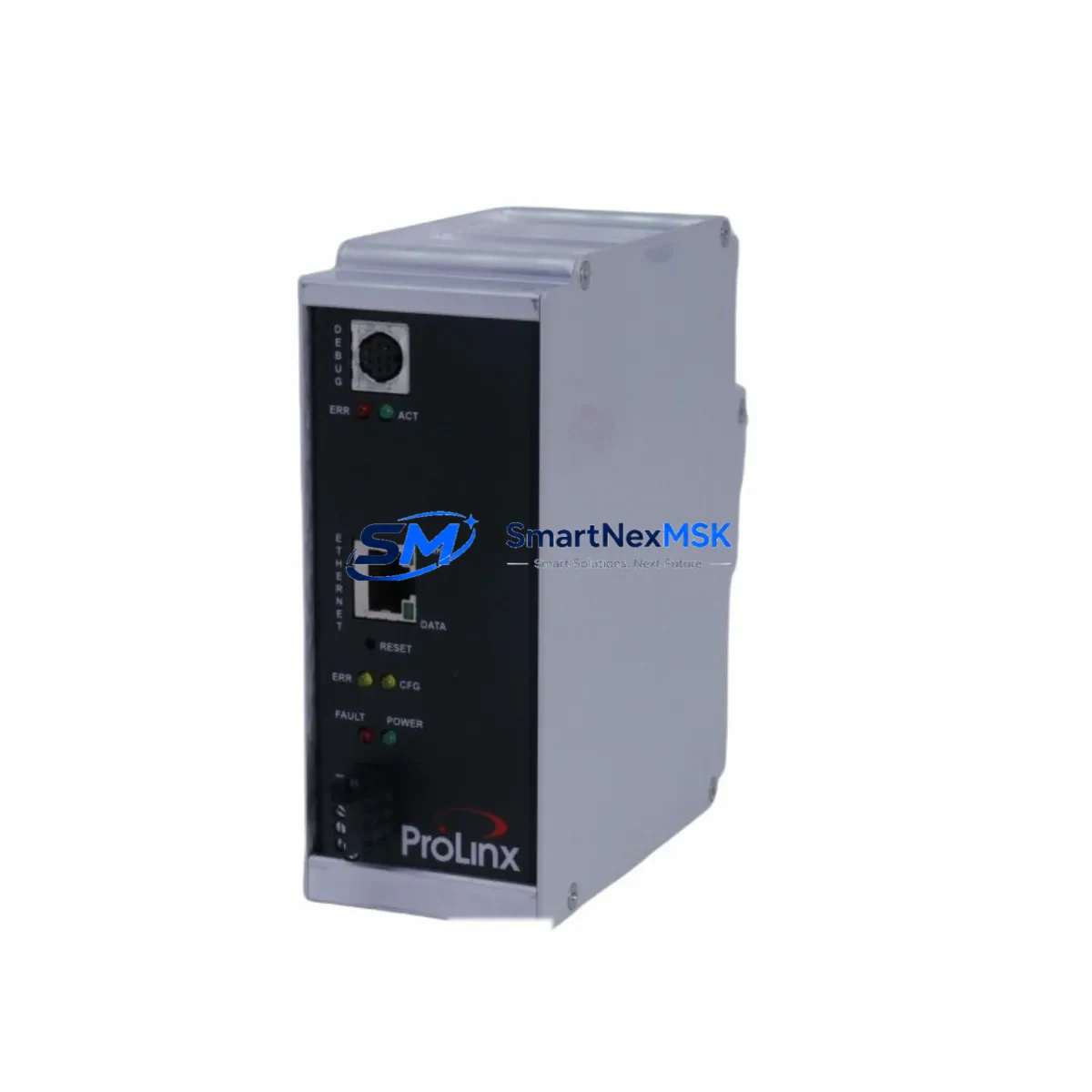
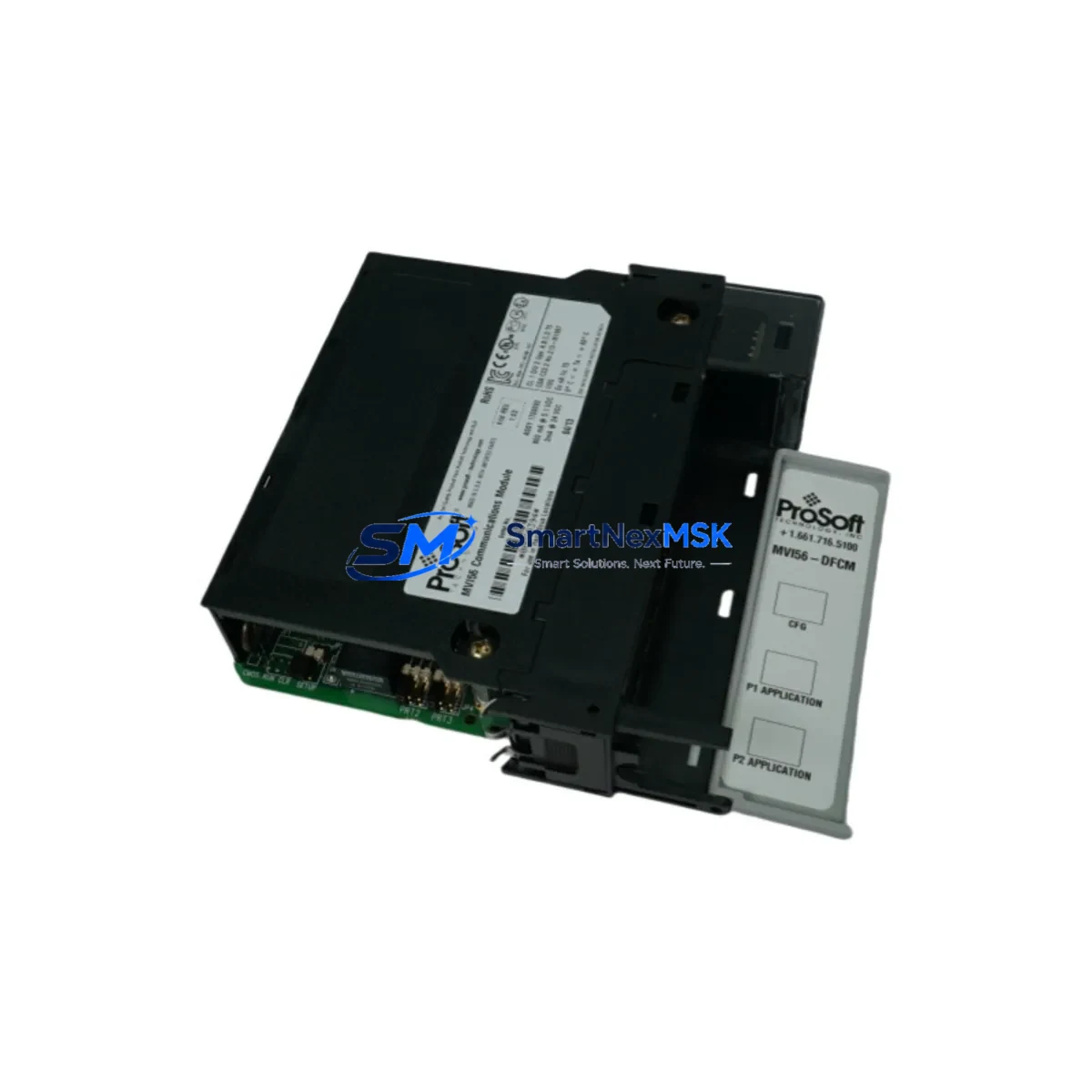
The ProSoft MVI69-104S is an IEC 60870-5-104 Ethernet server communication module engineered for Allen-Bradley CompactLogix platforms. Designed as a direct retrofit solution for aging SCADA infrastructure, the MVI69-104S enables power utilities, substations, and industrial automation facilities to migrate from discontinued or end-of-life communication hardware without replacing the entire control architecture. Whether you are upgrading a legacy RTU-based substation, replacing a failed communication card in a live control cabinet, or migrating from an older ProSoft MVI56-104S installed in a ControlLogix rack, this module delivers the protocol compatibility and physical form factor required for a low-risk, minimum-downtime transition.
The MVI69-104S occupies a single slot in the CompactLogix 1769 backplane and communicates directly with the L3x or L4x series controllers via the local I/O bus. It supports up to four simultaneous IEC 60870-5-104 TCP/IP client connections, making it suitable for multi-master SCADA environments where redundant control center polling is required. Configuration is performed through ProSoft Configuration Builder (PCB), and the module’s data map integrates cleanly into existing RSLogix 5000 or Studio 5000 Logix Designer tag structures, preserving program logic developed for earlier communication architectures.
Upgrade Compatibility Table
| Parameter | MVI69-104S (This Module) | Retrofit Notes |
|---|---|---|
| Platform Compatibility | CompactLogix 1769 (L23, L31, L32, L33, L35, L43, L45) | Not compatible with ControlLogix 1756 backplane — use MVI56-104S for that platform |
| Backplane Interface | 1769 local I/O bus, single slot | Verify available slot count; module must be within 8 slots of the controller |
| Communication Protocol | IEC 60870-5-104 (TCP/IP, server mode) | Replaces serial IEC 60870-5-101 setups when migrating to Ethernet SCADA |
| Power Consumption | 800 mA @ 5 VDC (backplane) | Verify 1769-PA2 or 1769-PB2 power supply capacity before installation |
| Ethernet Port | RJ-45, 10/100 Mbps | Assign static IP; confirm subnet matches SCADA master network segment |
| Max Client Connections | 4 simultaneous TCP/IP masters | Suitable for dual-redundant SCADA + engineering workstation polling |
| Configuration Tool | ProSoft Configuration Builder (PCB) | Import existing PCB project files from MVI69-101 or MVI69-104 for faster migration |
| Replacement Path | Replaces MVI69-104, MVI69-101, legacy serial RTU cards | Data object mapping must be verified against SCADA master point list |
| Debugging Support | LED status indicators + PCB diagnostics | Use PCB online monitor to verify ASDU transmission during commissioning |
| Warranty | 12-Month Warranty | Covered from date of shipment; includes functional test certification |
Retrofit Planning for Existing Automation Systems
A successful MVI69-104S retrofit begins well before the module arrives on site. The first step is a thorough audit of the existing CompactLogix rack configuration. Engineers should document every module currently installed — including any 1769-IQ16 digital input modules, 1769-OB16 digital output modules, 1769-IF4 analog input cards, and the 1769-L32E or similar controller — and calculate the total backplane current draw to confirm the existing 1769-PA2 power supply can accommodate the MVI69-104S’s 800 mA demand without exceeding the supply’s rated output.
Terminal wiring for the Ethernet port is straightforward — a standard Cat5e or Cat6 patch cable connects the module’s RJ-45 port to the plant network switch — but the network architecture deserves careful attention. If the existing SCADA system was previously communicating via a serial IEC 60870-5-101 link through a legacy protocol converter or a dedicated serial communication module, the migration to IEC 104 over Ethernet requires the SCADA master to be reconfigured with the new IP address, port number (default TCP 2404), and common address of ASDU. Coordinate this change with the SCADA vendor or control center operator before the cutover window.
Module addressing within the CompactLogix system is handled through the Studio 5000 I/O tree. The MVI69-104S appears as a generic 1769 module and requires a custom module definition with the correct input and output assembly sizes. Engineers migrating from an older MVI69-104 or MVI69-101 will find that the tag structure is largely preserved, though the data block sizes and configuration file layout should be cross-referenced against the MVI69-104S user manual to identify any differences in the M0/M1 file organization. If the original program used MSG instructions to read configuration data from the module, those instructions must be updated to reflect the new module’s slot address and data file references.
HMI screen updates are often overlooked during communication module retrofits. If the facility uses a PanelView Plus 7 or an older PanelView 1000 terminal connected to the CompactLogix controller, verify that all tag references in the FactoryTalk View ME application still resolve correctly after the module slot change. In cases where the MVI69-104S replaces a module in a different slot position, the controller tag addresses for the module’s input and output data tables will shift, requiring a global tag search-and-replace in the HMI project before going live.
For systems that also include a 1769-SDN DeviceNet Scanner or a 1769-ASCII serial module sharing the same rack, confirm that the total slot count does not exceed the controller’s local I/O expansion limit. CompactLogix L3x controllers support up to 8 local 1769 expansion modules, while L4x controllers support up to 16. If the rack is already near capacity, consider whether a 1769-ECR end cap repositioning or a rack expansion is required before the MVI69-104S can be physically installed.
Downtime Control During System Migration
Minimizing production downtime during a communication module replacement requires a structured cutover plan. Begin by exporting the full Studio 5000 project from the controller and saving a verified offline backup — this preserves the original program logic, force tables, and I/O configuration in the event that the migration needs to be rolled back. Similarly, export the existing ProSoft Configuration Builder project if a previous MVI69-series module was in service, as the configuration parameters (IP address, ASDU common address, data object mapping) will serve as the baseline for the new MVI69-104S configuration.
Where process conditions allow, perform a staged cutover: install and configure the MVI69-104S in a test rack or a spare slot before the scheduled maintenance window, verify communication with the SCADA master in a parallel test environment, and only perform the live swap during a planned outage. If a parallel test environment is not available, pre-stage the module with its IP address and PCB configuration loaded via the module’s USB configuration port before installation, so that the time the rack is de-energized is limited to the physical swap and Studio 5000 download only.
During the live cutover, follow this sequence: place the controller in Program mode, remove the old module, insert the MVI69-104S, update the I/O tree in Studio 5000 to recognize the new module definition, download the updated project to the controller, and return to Run mode. The SCADA master should re-establish its IEC 104 TCP connection within seconds of the module initializing. Monitor the module’s LED indicators — the APP and BP ACT LEDs confirm backplane communication and application activity respectively — and use the PCB online diagnostic tool to verify that data objects are being transmitted correctly before releasing the system back to operations.
All units supplied by SMARTNEXMSK are covered by a 12-month warranty from the date of shipment and undergo functional testing prior to dispatch, reducing the risk of a failed module causing an extended outage.
Retrofit Support FAQ
Q: Can the MVI69-104S directly replace an MVI69-104 or MVI69-101 without reprogramming the controller?
A: In most cases, the MVI69-104S can replace an MVI69-104 with minimal program changes. The module occupies the same backplane slot type and uses a similar data block structure. However, engineers should compare the M0/M1 file layouts between the two firmware versions and verify that all MSG instruction parameters are updated to match the new module’s assembly sizes. Replacing an MVI69-101 (IEC 101 serial) with the MVI69-104S (IEC 104 Ethernet) also requires reconfiguring the SCADA master for TCP/IP connectivity.
Q: What wiring changes are required when installing the MVI69-104S?
A: The MVI69-104S draws power from the 1769 backplane — no external power wiring is required. The only field connection is the Ethernet cable to the plant network. If the previous module used serial RS-232 or RS-485 wiring, those cables can be removed. Confirm that the 1769-PA2 or 1769-PB2 power supply has sufficient remaining current capacity (minimum 800 mA at 5 VDC) before energizing the rack.
Q: How is compatibility with the SCADA master verified before the live cutover?
A: Use ProSoft Configuration Builder’s online diagnostic mode to monitor IEC 104 ASDU transmission in real time. Connect a laptop running PCB to the module’s USB port, establish an online connection, and observe the data object status table. Confirm that the SCADA master’s IP address appears in the active connection list and that spontaneous data (Class 1) and general interrogation responses are being exchanged correctly. This verification step should be completed before the maintenance window ends.
Q: What does the 12-month warranty cover, and what is the return process?
A: The 12-month warranty covers manufacturing defects and functional failures under normal operating conditions. Each unit is tested prior to shipment and ships with a test certification record. In the event of a warranty claim, contact SMARTNEXMSK at [email protected] with the order number and a description of the fault. Replacement units are dispatched promptly to minimize system downtime, and failed units are returned for inspection via the RMA process outlined at the time of claim.
© 2026 SMARTNEXMSK. All rights reserved.
Original Source: https://smartnexmsk.com
Contact: [email protected] | +86 18259474341